SDM-6000 Components • 8
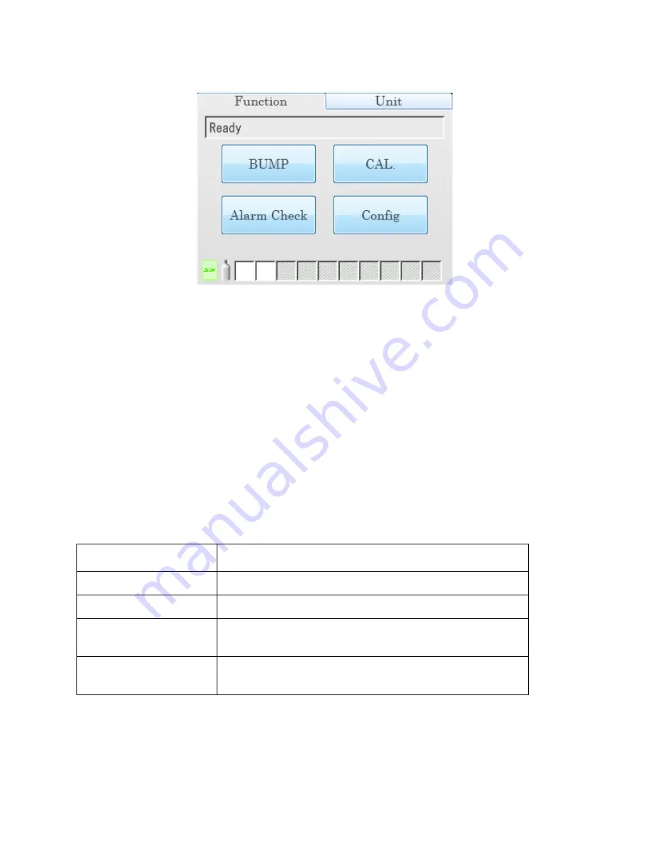
Function Tab
Figure 4: Function Tab
The Function Tab allows the user to:
•
initiate a bump test
•
initiate a calibration
•
initiate an alarm check
•
set operational parameters
It is present on the touch screen of a single SDM-6000 system and on the touch
screen of the master (leftmost) SDM-6000 in a multi-SDM-6000 system. It has the
same appearance in both systems. The text field above the BUMP and CAL buttons
shows instrument or station status.
The SD card logo in the bottom left corner of the Function Tab indicates whether an
SD card is inserted in the SD card slot and the status of an inserted SD card.
Table 3: SD Card Logo Colors
The cylinder logo in the bottom left corner of the Function Tab indicates the expiration
status of the calibration cylinders. In order to set up the expiration status, the docking
station must be connected to the PC Controller Program and the cylinder information
entered into the Cylinders Tab. If the docking station is never connected to the PC
SD Card Logo Color
Meaning
Gray
No SD card inserted.
Green
More than 20% of the SD card’s memory is available.
Yellow
Less than 20% but more than 1 MB (approximately
946 tests) of the SD card’s memory is available.
Red
Less than 1 MB (approximately 946 tests) of the SD
card’s memory is available.


