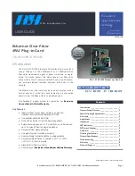
RLH 10/100/1000 4RU
Ethernet over Fiber Card
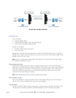
RLH 10/100/1000 4RU
Ethernet over Fiber Card
24 - 56VDC Power Supply
24 - 56VDC Power Supply
Network
or
Ethernet
Device
Network
or
Ethernet
Device
Ethernet
Ethernet
Fiber Optic Cable
Up to 120km / 74 miles
Typical
Ethernet System Diagram
Installation
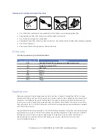
Prior to installation:
•
Check for shipping damage
•
Check the contents to ensure correct model and fiber type
•
Have a clean, dry installation environment ready
Required for installation:
•
24-56VDC (3W minimum) power source
•
RLH card housing
Measure the DC voltage of the source power to ensure that it is 24-56VDC (3W minimum). All electrical
and fiber optic connection are made directly onto the card. The Ethernet over fiber card is designed to be
installed into any RLH card housing.
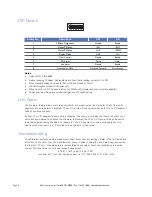
Note:
In order to maintain high voltage isolation, Fiber Optic Link CO and Sub cards must be powered
from separate isolated power sources.
Connect fiber optic cable
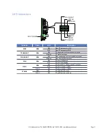
Multimode and single-mode Ethernet cards are equipped with either two ST, SC or FC female optical
connectors, or a single bi-directional connector (SC only). Connect fibers to the Transmit (TX) and Receive
(RX) optical connectors. The other end of the fiber may be connected to another 10/100/1000 Ethernet
card or any 1000SX/LX Ethernet device. For bi-directional, single fiber models, there is only one SC
connector used for transmitting and receiving.
Note
: Fiber cable should always be routed loosely avoiding tight bends.
Connect Ethernet cable
The 10/100/1000Base-T copper connection is made via the RJ45 port located on the front of the card
with. The TP port is auto-negotiating and requires no special settings.
Connect Power
Connect a 24-56VDC (200mA minimum) power source to the screw-down terminal on the Ethernet card.
The power input is not polarity sensitive. The terminal unplugs from the card to make wiring easier
Page 4
RLH Industries, Inc. • Tel. 866-DO-FIBER • Fax 714 532-1885 • www.fiberopticlink.com

