background image

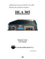
HLA 305


2


1. Introduzione


L'amplificatore HLA305 è un amplificatore lineare ad alte prestazioni costruito per essere utilizza-
to con tutti i ricetrasmettitori HF in tutte le modalità di trasmissione. 
Questo amplificatore utilizza quattro dispositivi bipolari MRF455 configurati in classe AB. 
Opera in tutte le bande da 160 a 10 metri in maniera lineare e senza interruzioni da 1,5 e 
30MHz*.  
Una ventilazione forzata (HLA305V) a velocità variabile provvede al raffreddamento di tutte le 
parti dell'amplificatore, un circuito elettronico controllato da un microprocessore ne controlla il fun-
zionamento. 
Un display LCD, vi tiene sempre informati sui parametri fondamentali dell'amplificatore. Tempera-
tura dissipatore, banda impostata e molte altre informazioni sono visualizzabili per avere sotto 
controllo in ogni momento lo stato di funzionamento dell'amplificatore. 
Vi raccomandiamo la lettura del presente manuale in tutte le sue parti prima della messa in fun-
zione dell'amplificatore. 
Conoscere il funzionamento di tutte le sezioni dell'amplificatore vi permetterà un uso più perfor-
mante ed eviterà errori che, oltre a causare una perdita di potenza in uscita, potrebbero determi-
nare danni ai componenti anche in maniera irreversibile. 
Un uso attento e corretto vi farà apprezzare le "performance" dell’HLA 305 per molti anni senza 
nessun intervento tecnico. 


Introduction


The HLA 305 Linear Amplifier is a high performance amplifier designed for use with all HF trans-
ceivers and all modes of transmission. 
The amplifier uses four MRF455 configured for Class AB operation. 
Operation is possible for all  amateur bands from 160 to 10 meters and without interruption from 
1.5 to 30 MHz.*  
The HLA305V features microprocessor controlled variable speed forced air cooling. 
An LCD display shows all of the amplifiers operational parameters; Heat-sink temperature, filter 
band and other parameters, enabling the operator to see the state of the amplifier at any time. 
This allows the user to obtain the maximum performance and avoid any possible operating errors 
resulting in a loss of output power and possible irreversible component damage. 
Attention to correct operating procedure and operating the amplifier within it’s capabilities will re-
sult in optimum performance and many years of trouble free use. 
 
(* USA Model band blocked 26-28MHz to comply with FCC: 

§97.317

)


Summary of Contents for HLA305

Page 1: ...1 Manuale Utente User Manual Costruzioni Elettroniche S n c www rmitaly com Amplificatore Lineare per bande HF a stato solido Solid State HF Linear Power Amplifier HLA 305...

Page 2: ...rfor mante ed eviter errori che oltre a causare una perdita di potenza in uscita potrebbero determi nare danni ai componenti anche in maniera irreversibile Un uso attento e corretto vi far apprezzare...

Page 3: ...Off 8 7 4 3 2 HI Off 8 7 4 3 3 Power ON Off 8 8 Protezioni 8 8 1 OVER Input Power 8 8 2 OVER Temp 8 8 3 SWR 8 8 4 FILTER FAULT 8 8 5 Error Frequency 8 9 Garanzia 9 Schema elettrico 12 Scheda per assis...

Page 4: ...ransistor di potenza Final Transistor MRF 455 x 4 Configurazione Circuit Class AB push pull Metodo diraffreddamento Cooling Method ForcedAir Cooling HLA305V Microprocessore MPU PIC 18F4620 LCD Tempera...

Page 5: ...HLA 305 5...

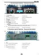
Page 6: ...G Indica una condizione di allarme eccessiva potenza Indicates excessive input power high temperature and d ingresso eccessiva temperatura allarme generico general alarm fault conditions 8 TX Indica c...

Page 7: ...ficare che l impianto di terra della stazione sia di ottima qualit questo elimi ner molti disturbi in ricezione preverr accumulo di cariche statiche ed eviter che ci siano punti a tensione RF elevata...

Page 8: ...SSB Off Fig 1 Quando attivo permette di inserire un ritardo nel rilascio del rel di antenna in caso di uso in SSB o CW se l amplificatore connesso al ricetrasmetitore tramite la connessione PTT Fig 2...

Page 9: ...to use the amplifier by utilising the internal VOX circuit For the best control of TX RX switching it is recom mend that the PTT input is utilised The PTT input connector is an RCA Phono type Use a sh...

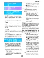
Page 10: ...3 MENU When the amplifier is switched on in receive mode Fig 1 ON Fig 1 OFF and the band selector set to Auto it is possible to access the settings menu Press the button SET trough the hole Fig 1 usin...

Page 11: ...It will then be necessary to restart the amplifier by switching the amplifier off and then back on to reset the protection 18 2 OVER Temp The temperature at the point of contact between the transisto...

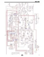
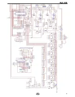
Page 12: ...HLA 305 12...

Page 13: ...HLA 305 13...

Page 14: ...14 Certification and Approvals This power amplifier has been tested and found comply to FCC rules 97 315 and 97 317 regarding the Spurious and Mean power emissions as request for 97 307 FCC ID 2ACTRH...

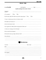
Page 15: ...el Yes No If not set to maximum power what is the maximum value What band does the fault occur What is the transmission mode How long does the amplifier operate normally before the fault occurs Is the...

Reviews: