User's Guide HDSP System Multiface II
© RME
53
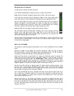
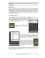
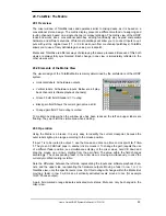
28.3 Elements of a Channel
A single channel consists of various elements:
Input channels and playback channels each have a mute and solo button.
Below there is the panpot, realized as indicator bar (L/R) in order to save space.
In the field below, the present level is displayed in RMS or Peak, being updated about
every half a second. Overs (overload) are indicated here by an additional red dot.
Next is the fader with a level meter. The meter shows both peak values (zero attack, 1
sample is enough for a full scale display) by means of a yellow line, and mathemati-
cally correct RMS values by means of a green bar. The RMS display has a relatively
slow time constant, so that it shows the average loudness quite well.
Below the fader, the current gain and panorama values are shown.
The white area shows the channel name. Selecting one or more channels is done by
clicking on the white label which turns orange then. A click in the third row with
pressed Ctrl-key activates internal loopback mode, the label turns red. A right mouse
click opens a dialog to type in a new name.
The black area (routing field) shows the current routing target. A mouse click opens the routing
window to select a routing target. The list shows all currently activated routings by checkmarks
in front of the routing targets.
28.4 Tour de TotalMix
This chapter is a practical guide and introduction on how to use TotalMix and on how TotalMix
works.
Starting up TotalMix the last settings are recalled automatically. When executing the applica-
tion for the first time, a default file is loaded, sending all playback tracks 1:1 to the correspond-
ing hardware outputs with 0 dB gain, and activating phones monitoring.
Hold down Ctrl and click on preset button 1 to make sure that factory preset 1 is loaded. The
faders in the top row are set to maximum attenuation (called m.a. in the following), so there is
no monitoring of the input channels. The
Submix View
is active, therefore for improved over-
view all outputs except Phones are greyed out. Additionally all faders are set to the routing
target Phones. All faders of the middle row are set to 0 dB, so no matter on which channels a
playback happens, the audio will be audible via the Phones output. Just try it!
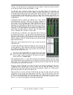
We will now create a submix on analog outputs 1/2. Please start a multitrack playback. In the
third row, click on the channels of hardware output AN1 or AN2. The Submix View changes
from Phones to AN1/AN2. Both the fader settings and the output levels of all other channels
are still visible, but greyed out for improved orientation.
As soon as AN1/AN2 became active, all faders of the second row jumped to their bottom posi-
tion – except those of playback channel 1/2. This is correct, because as mentioned above the
factory preset includes a 1:1 routing. Click on AN 3/4 and the faders above are the only active
ones, same for AN5/6 and so on.
Back to AN1/2. Now you can change all the faders of all inputs and playback channels just as
you like, thus making any input and playback signals audible via the outputs AN1/2. The pano-
rama can be changed too. Click into the area above the fader and drag the green bar in order
to set the panorama between left and right. The level meters of the third row display the level
changes in real-time.
Summary of Contents for Hammerfall Multiface II
Page 5: ...User s Guide HDSP System Multiface II RME 5 User s Guide Multiface II General...
Page 14: ...14 User s Guide HDSP System Multiface II RME...
Page 51: ...User s Guide HDSP System Multiface II RME 51...
Page 71: ...User s Guide HDSP System Multiface II RME 71 User s Guide Multiface II Technical Reference...
Page 80: ...80 User s Guide HDSP System Multiface II RME 35 Diagrams 35 1 Block Diagram Multiface II...


