background image


Specifications 

Operating Instructions for the TERZ 94 Electronic Turbine Meter 

45


Vo or RS-485 data interface 

In the case of the explosion-protected (Ex) design, the device can only be 
connected to a certified intrinsically safe circuit. (For Ex connected loads, see 
approval certificate.) 
 

Vo data interface:


Internal


Connector (Binder)


Terminals: X15,4 

(+) 

 X15,3 

(-) 


X15,1 and X15,2 open 

 
U

min

: 7.0


U

i

: 13.5


I

i

: 15


mA 

P

i

: 210


mW 

External capacitance: 

2,5 µF 

External inductance: 

1 H 

Ex separating unit: 

KFD2-ST2-Ex1.LB (Fuchs) 


RS-485 data interface: 

Terminals: 

X15,4 (+ supply) 


X15,3 (- supply) 


X15,2 (line A) 


X15,1 (line B) 

 
U

min

: 7.0


U

i

: 10.5


I

i

: 428


mA 

P

i

: 900


mW 

Internal capacitance: 

1,32 µF 

Internal inductance: 

600 µH 

External capacitance: 

23,7 µF 

External inductance: 

1 H 

Ex separating unit: 

17-21S1-S111 / EExi (Bartec) 

 
NOTE: If the EZD protocol or the RS485 bus is used, the device is supplied 
via the data interface. 

Summary of Contents for TERZ 94

Page 1: ...ns RMG Me technik GmbH Otto Hahn Strasse 5 35510 Butzbach Germany P O Box 280 35502 Butzbach Germany Tel 49 6033 897 0 Fax 49 6033 897 130 Status 12 04 Serving the Gas Industry WORLDWIDE Electronic Tu...

Page 2: ......

Page 3: ...alizing unit 14 Operation 15 Display 15 Programming 17 Parameters and Modes of the TERZ 94 94 S 21 Power Supply 27 Maintenance 28 Lubrication 28 Changing the battery 29 Specifications 30 Measuring ran...

Page 4: ...d by long term stability and low wear The TERZ 94 94 S is provided with HF and LF outputs which allow the device to be used as a flow transducer for control applications and remote transmission Featur...

Page 5: ...scription Construction Part Designation Material 1 Meter head 2 Set screw Steel 3 Sensor WF01 1 channel or WF02 2 channels 4 Permanent magnet Oerstit 500 5 Lubricator from DN 200 6 Radial ball bearing...

Page 6: ...Functional Description 4 Operating Instructions for the TERZ 94 Electronic Turbine Meter 9 O ring 10 Sensor sleeve with sensor Nirosta steel 11 O ring 8x2 5 83FKM592...

Page 7: ...of the turbine wheel This pulse is further processed by the electronic system of the meter head 1 Meter head Inside the meter head the number of pulses is divided by the meter factor number of pulses...

Page 8: ...dule TERZ94trm which serves as power supply and 4 to 20 mA current output at the same time For this purpose a power supply unit is required which is to be connected to this output The TERZ 94 S cannot...

Page 9: ...tions for the TERZ 91 Electronic Turbine Meter 7 TERZ 94 2 channel Channel 1 Channel 2 1 K 12345678 m3 HF output LF output 1 n f i Current output 1 n Alarm contact Option EZD or RS485 interface With 2...

Page 10: ...approved for use in areas subject to explosion hazards and its code is II 2 G EEx ib ia IIC T3 T4 The appropriate certificate of conformity can be found in the annex and its reference number is T V 02...

Page 11: ...Safety Instructions Operating Instructions for the TERZ 94 Electronic Turbine Meter 9...

Page 12: ...e Methane Helium Ethane Carbon dioxide dry Propane Nitrogen Butane Hydrogen Special designs PTFE lining special lubrication special material etc can be used for corrosive and humid gases such as Ethyl...

Page 13: ...he exact value is calculated from the pressure loss which is determined on testing the volumeter Example of calculation QM 650 m3 h DN 150 1 3 kg m3 natural gas 600 mbar mbar 5 5 150 650 3 1 5040 DN Q...

Page 14: ...ak You can install the meter head also vertically To do this you must proceed as follows Unscrew the cover of the meter head Disconnect the two wires from terminal X5 remember the polarity Loosen the...

Page 15: ...hat the limiting values from the conformity certificate see appendix for the devices which have to be connected are not exceeded If one or more electric circuits are used it is to ensure that with the...

Page 16: ...Z90 Meter head mounted on meter case 3 5 and 4 6 all open Remote totalizing unit 3 5 and 4 6 1 2 and 3 4 for 2 channel measurement only TERZ 94 Controlling the start stop totalizer or resetting the re...

Page 17: ...Electronic Turbine Meter 15 As soon as input X5 terminals 1 2 has been short circuited through an external contact interruption or resetting is performed For this purpose set jumpers at the positions...

Page 18: ...of the housing To connect the cables to the spring terminals you need a screwdriver with a blade width of a maximum of 2 5 mm Introduce the blade into the intended slot and press down the screwdriver...

Page 19: ...tructions for the TERZ 94 Electronic Turbine Meter 17 connection control input The shielding must always be connected to earth on both sides In the case of the TERZ 94 you must proceed as described in...

Page 20: ...ited by the limit values for intrinsically safe circuits and depends on the inductance and capacitance of the cable Cable glands Clamp the shielding on both sides as shown in the picture below into th...

Page 21: ...Installation Operating Instructions for the TERZ 94 Electronic Turbine Meter 19...

Page 22: ...delivered Should this not be the case you will have to connect the connecting cable to Input terminal X5 clamp 3 and clamp 4 of the display board and the terminals marked Z hlwerk Index Input on the...

Page 23: ...Installation Operating Instructions for the TERZ 94 Electronic Turbine Meter 21...

Page 24: ...ble No damage will occur in the case of a return flow without shocks Before starting up the device make sure that all lines have been correctly installed and connected in the terminal compartment The...

Page 25: ...the main totalizer will appear again If the display of the TERZ 94 does not show anything the device is in energy saving mode In this mode the display is switched off However incoming pulses are proce...

Page 26: ...nic Turbine Meter 1 Pulse scaler 000 0 0 0 0 1 MOD Configuration 0000008000 S No Serial number Extra values for the TERZ 94 S 80 38 Hz Frequency sensor 0 0 0 0 5 8 3 1 m3 Main totalizer An overview of...

Page 27: ...ng the button for a longer time more than 2 seconds will activate all segments of the display segment test and then the display will switch over to showing the Vm totalizer The following text describe...

Page 28: ...g mode Press the button longer than 2 seconds Programming mode Set the decimal point Display mode Switch over to the next higher level Programming mode Increase the decimal by 1 Scroll in the list Val...

Page 29: ...shing decimal by pressing either or 1 or or 1 Example If you press the button three times the first decimal will be increased from 0 to 3 If an L appears on the far left side of the display this value...

Page 30: ...uency etc are display values and cannot be directly modified However there are many parameters which influence the formation of these measured values These parameters are described in the following se...

Page 31: ...etres are directly displayed Its value can be read from a label located on the left side of the case Any modification of this adjustment is within the sphere of responsibility of the operating company...

Page 32: ...Operation 30 Operating Instructions for the TERZ 94 Electronic Turbine Meter Hz 5 10 Hz 2362 3600 16 fmin Hz 164 Hz 2326 3600 250 fmax...

Page 33: ...frequency of the LF pulses not on the display The number of displayed digits after decimal point or a multiplier are programmed as an operating mode A08 Recommended values values set in the factory D...

Page 34: ...ostics no influence on the metering result 0 Menu for standard operation 1 Menu for service 9 All parameters visible Main totalizer mode This parameter defines the unit for the gas volume 0 m3 cubic m...

Page 35: ...Operation Operating Instructions for the TERZ 94 Electronic Turbine Meter 33 3 Test protocol...

Page 36: ...ating modes at the moment 0 ENCO F 1 ENCO M 2 TERZ 94 1 channel 3 TERZ 94 1 channel with start stop totalizer 4 TERZ 94 1 channel with reset totalizer 5 TRZ03 TE TEL 2 channels with pulse monitoring S...

Page 37: ...ed current of 4 mA Generally the minimum flow rate Qmin of the meter is set here This setting is made in the factory 6 Flow rate at 20 mA With this parameter you set the flow rate in m3 h which corres...

Page 38: ...Operation 36 Operating Instructions for the TERZ 94 Electronic Turbine Meter All other values are not permitted...

Page 39: ...for D are 0 to 0 9 Output current 1 D x value D x old value 10 Correction factors for current offset and current rise The current output is adjusted in the factory through two correction factors offs...

Page 40: ...al on the device being read once a week or woken up by pressing the external button 2 If an interface module is used for transmitting data such as the ENCO with external supply the service life of the...

Page 41: ...months 2 strokes DN 200 DN 250 PN 25 to 100 ANSI 300 to 600 PN 10 to 16 ANSI 150 Small oil pump pushbutton operated Every 3 months 6 strokes DN 250 from DN 300 PN 25 to 100 ANSI 300 to 600 all pressur...

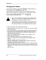
Page 42: ...battery you must proceed as follows Remove the cover of the meter head on the rear side there is the battery fixed with cable ties If the meter is located in an area subject to explosion hazards disco...

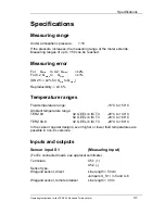
Page 43: ...lity 0 5 Temperature ranges Fluid temperature range 10 C to 50 C Ambient temperature range TERZ 94 II2 G EEx ib IIC T4 20 C to 40 C II2 G EEx ib IIC T3 20 C to 60 C TERZ 94 S II2 G EEx ib IIC T4 20 C...

Page 44: ...Specifications 42 Operating Instructions for the TERZ 94 Electronic Turbine Meter Jumpers X_S1 3 5 and 4 6 Jumpers X_TERZ90 1 2 Reed contact Jumpers X_S1 1 3 and 2 4...

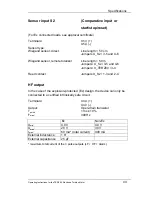
Page 45: ...totalizer Line length 50 m Jumpers X_S2 3 5 and 4 6 Jumpers X_TERZ90 3 4 Reed contact Jumpers X_S2 1 3 and 2 4 HF output In the case of the explosion protected Ex design the device can only be connec...

Page 46: ...V 4 0 V Umax 28 V 30 V Imax 60 mA total current 400 mA External inductance 1 H External capacitance 25 F maximum total current of the 3 pulse outputs LF HF Alarm Alarm output In the case of the explo...

Page 47: ...4 X15 3 1 X15 1 and X15 2 open Umin 7 0 V Ui 13 5 V Ii 15 mA Pi 210 mW External capacitance 2 5 F External inductance 1 H Ex separating unit KFD2 ST2 Ex1 LB Pepperl Fuchs RS 485 data interface Termina...

Page 48: ...Current loop connection TERZ 94 S only Terminals X22 1 X22 2 Uext min 12 V Uext max 28 V Imin 3 5 mA Imax 23 mA External load max RLmax Uext 10 V Imax in e g Uext 16 V RLmax 16 V 10 V 23 mA 260 Curre...

Page 49: ...cations Operating Instructions for the TERZ 94 Electronic Turbine Meter 47 Spheroidal cast iron or steel depending on the pressure class and the nominal diameter Aluminium is used for the threaded end...

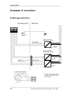
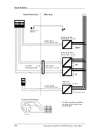
Page 50: ...lating amplifiers KFD2 SOT Ex2 24 V DC pulse outputs LIYCY 2x2x0 75 mm blue 2 X4 1 2 3 4 5 6 24 V DC PE 3 6 3 1 4 1 7 9 7 11 11 12 12 PE PE 8 10 8 Alarm HF LF 11 12 PE isolating amplifier KFD2 SOT Ex1...

Page 51: ...Specifications Operating Instructions for the TERZ 94 Electronic Turbine Meter 49 Main powered device Ex design Connection only via the current module with built in backup battery...

Page 52: ...2x2x0 75 mm blue 2 24 V DC PE 3 6 3 1 4 1 7 9 7 11 11 12 12 PE PE 8 10 8 Alarm HF LF 11 12 PE isolating amplifier KFD2 SOT Ex1 24 V DC alarm output LIYCY 2x0 75 mm blue 2 current output LIYCY 2x0 75 m...

Page 53: ...Specifications Operating Instructions for the TERZ 94 Electronic Turbine Meter 51 Main powered device Non Ex design Connection only via the current module with built in backup battery...

Page 54: ...und Alarmausgang U 30 V Maximale Summe der Str me in allen 3 Ausg ngen 400 mA max Safe area connector Binder series 693 supply unit KFD2 STC3 Ex1 24 V DC outputs LIYCY 3x2x0 75 mm blue 2 alarm output...

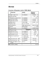
Page 55: ...six digits 12 3456 P m A07 Pulse scaler 0 01 0 1 1 10 100 L 1 A08 Configuration TERZ operating mode 00011021 MOD A09 Error Rolling display 0 ERR B01 Serial number 0 to 99999999 12345678 MOD C01 Curren...

Page 56: ...l DN50 100 7700 1 00110102 00110109 00110112 00110119 0 100 1 0 7 DN40 65 7750 1 00110102 00110109 00110112 00110119 0 65 1 0 7 Settings DN25 25 13000 10 00110102 00110109 00110112 00110119 0 25 varia...

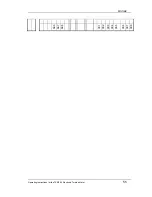
Page 57: ...Annex Operating Instructions for the TERZ 94 Electronic Turbine Meter 55 A06 A07 A08 C01 C02 C03 C04 C05 C06 C07 C08...

Page 58: ...DN250 2500 75 1 00110202 00110209 00110212 00110219 0 2500 1 0 7 DN200 2500 80 1 00110202 00110209 00110212 00110219 0 2500 1 0 7 Settings DN200 1600 135 1 00110202 00110209 00110212 00110219 0 1600 v...

Page 59: ...Annex Operating Instructions for the TERZ 94 Electronic Turbine Meter 57 A06 A07 A08 C01 C02 C03 C04 C05 C06 C07 C08...

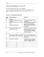
Page 60: ...changed 2 Pulse fault sensor loss 10 10000 X Y Check the electrical connection of the sensor Possibly the sensor must be exchanged 3 EEProm Hardware fault TERZ 94 PCB board must be exchanged 4 5 Curre...

Page 61: ...rate at 4 mA NO NO X X C03 Flow rate at 20 mA NO NO X X C04 Calibration current NO NO X X C05 Current output mode NO NO X X C06 Correction factor offset NO NO X X C07 Correction factor Rise NO NO X X...

Page 62: ...Annex 60 Operating Instructions for the TERZ 94 Electronic Turbine Meter mode are blanked out...

Page 63: ...y Mode 12345678 m3 P P Scrolling in the matrix upwards Scrolling in the matrix downwards 2 sec switch to the programming mode 2 sec switch to the coordinate Button at the rear of the board 2 sec chang...

Page 64: ...s for the TERZ 94 Electronic Turbine Meter Terz 94 Programming Mode 12345678 m3 P P Button at the rear of the board Flashing digit 1 Flashing digit 1 Set decimal point reset if float Abortion of progr...

Page 65: ...supply voltage 24V to terminal X22 1 2 Switch on the power supply 24 V Check the current output Set the current output in channel A09 to I Out mode 1 or 2 Channel C02 enter flow rate at 4mA Channel C...

Page 66: ...Abbreviations Basic type Control cable twisted cable Example Li Y C Y 2x 0 75 blue Sheath colour Conductor cross section mm2 Number of cores Sheath material Thermoplastic resins Special features Scree...

Reviews: