


Visit
www.rmspl.com.au
for the latest product information.
Due to RMS continuous product improvement policy this information is subject to change without notice. 1S25/Issue F/07/03/2011 - 2/9
ARC FAULT PROTECTION
The over-current caused by an arc is, due to its resistance, lower
than the over-current caused by a “metallic” short circuit. The
over-current caused by the arc may also be lower than the
protection start current when energising circuits or starting large
motors. The consequence of these conditions is that a protection
system based solely on over-current detection cannot effectively
discriminate between normal system currents & an arc fault
condition:
For moderate arc fault currents the trip time of the over-current
IDMT stage will be too slow;
For very low arc fault currents the instantaneous trip stage of a
standard over-current relay cannot be set low enough.
SWITCHGEAR ARC PROTECTION
The risk of arc fault damage exists at the CB cable termination &
in the CB chamber itself. The CB cable termination is particularly
at risk to ingress of moisture & rodent damage.
The 1S25 Arc Fault Monitor provides four (4) independent
tripping zones with one or two arc sensors per zone as depicted
in the single line application diagrams at right.
Figures 1 & 2 depict arc protection of up to four feeder circuits
with a single 1S25 as independent zones. A trip signal will be
initiated to the circuit breaker in the event of an arc fault occurring
at the sensor(s) within its zone provided the overcurrent relay
starter contact is picked up. In these applications the overcurrent
check stage is optional as the consequence of a single feeder
outage is less than the loss of an entire BUS.
Figure 3 shows an application where a 1S25 is applied for the
protection of the Cable box, CT chamber & CB chamber across
two feeder circuits (Zones). In this configuration one arc trip zone
is used to trip the feeder circuit breaker in the event of an arc
fault in the cable box or CT chamber. The second zone trip
output is wired to trip the upstream BUS breaker (BUS
overcurrent check not shown), in the event of an arc fault in the
CB chamber.
EXISTING SWITCHGEAR APPLICATIONS
The existing overcurrent relay protecting the feeder will normally
provide an independent output contact associated with the start
current setting of the relay. That is an output contact that will
close when a phase or earth fault current is detected above the
threshold which starts the internal relay timers. This starter
element should be set for instantaneous operation so that it will
pick up in the order of 15ms.
An Arc Fault Monitor relay 1S25 is installed on the switchgear
panel adjacent to the protection relay.
1S30 optical arc sensors are fitted in the cable termination box &
CT chamber as depicted in figure 2.
The overcurrent relay starter contact may optionally be wired in
series with the arc fault detection trip output contact as depicted
in figure 8. The resulting “AND” function trip output is wired to trip
the breaker in ~15ms in the event that an arc fault is detected
while the overcurrent start element is picked up.
The common arc trip & fail alarm contacts may be employed for
interface to a SCADA system for fault reporting.
NEW SWITCHGEAR APPLICATIONS
For new switchgear installations a modern numeric feeder
protection relay is likely to be employed which will have
numerous programming & configuration options.
The basic concept is the same as for the existing switchgear
application described above except that the additional features &
flexibility of modern feeder protection relay allows improved
system integration.
This may be achieved by using the common arc trip output
contact to interface to a programmable status input on the feeder
protection relay. Depending on the model of protection relay
being used this input may be programmed to provide an alarm
message on the HMI, time stamped event record available via its
communications link.
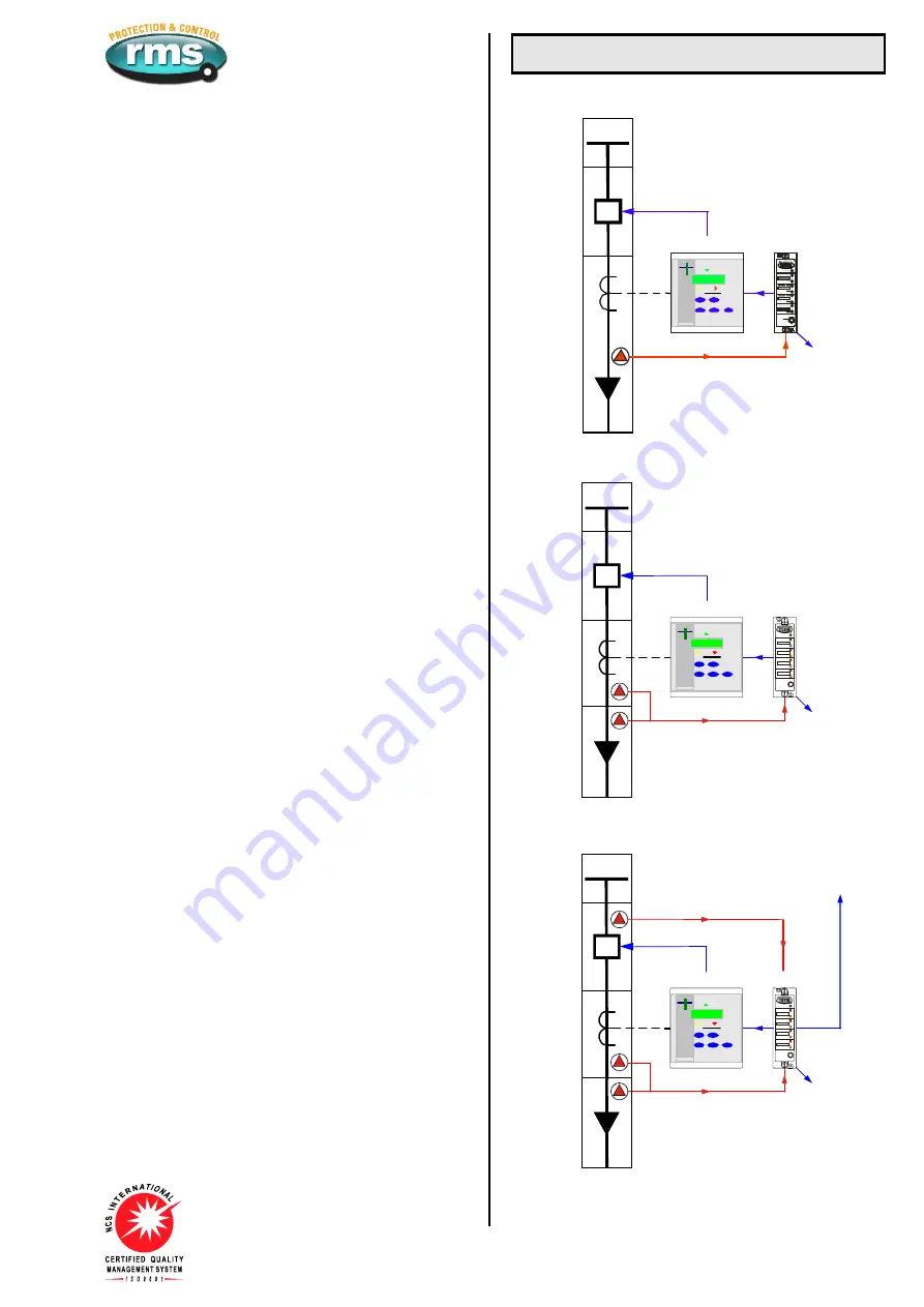
Switchgear Applications
ZONE 1
ARC PROTECTION
COMMON
ALARM
OUTPUT
1S25
50/51
Figure 1: Single arc sensor per zone 1 - Cable box
ZONE 1
ARC PROTECTION
COMMON
ALARM
OUTPUT
1S25
50/51
HEALTH Y
Z ONE 2
Z ONE 3
Z ONE 4
Z ONE 1
Cus tom te xt
Cus tom te xt
Cus tom te xt
Cus tom te xt
FAIL
FAIL
FAIL
FAIL
T RIP
T RIP
T RIP
T RIP
RESET
/T EST
Figure 2: Two arc sensors per zone - Cable box & CT chamber
ZONE 1
ARC PROTECTION
COMMON
ALARM
OUTPUT
1S25
50/51
HEALTH Y
Z ONE 2
Z ONE 3
Z ONE 4
Z ONE 1
Cus tom te xt
Cus tom te xt
Cus tom te xt
Cus tom te xt
FAIL
FAIL
FAIL
FAIL
T RIP
T RIP
T RIP
T RIP
RESET
/T EST
ZONE 2 TRIP
UP STREAM
BREAKER
ZONE 2
ARC PROTECTION
ZONE 1 TRIP
Figure 3: Two arc sensors in zone 1 - Cable box & CT chamber
One or two arc sensors in zone 2 for CB chamber


