


Visit
www.rmspl.com.au
for the latest product information.
Due to RMS continuous product improvement policy this information is subject to change without notice. 1S25/Issue F/07/03/2011 - 4/9
ZONE 1
ARC PROTECTION
COMMON
ALARM
OUTPUT
1S25
50/51
HEALTH Y
Z ONE 2
Z ONE 3
Z ONE 4
Z ONE 1
Cus tom te xt
Cus tom te xt
Cus tom te xt
Cus tom te xt
FAIL
FAIL
FAIL
FAIL
T RIP
T RIP
T RIP
T RIP
RESET
/T EST
TRIP
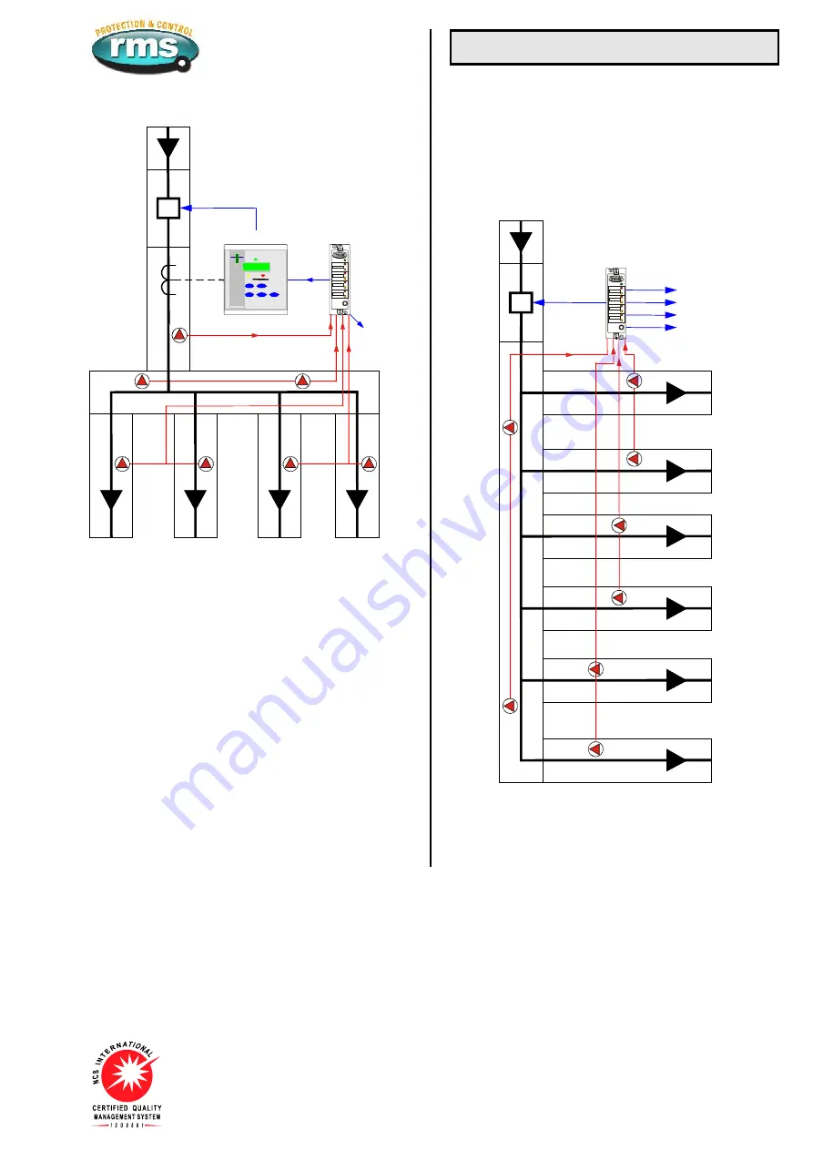
Figure 6:
Up to eight arc sensors distributed in low voltage switchgear.
Over current check stage depicted.
Low Voltage Applications
LOW VOLTAGE ARC PROTECTION
Figures 6 & 7 depict how the 1S25 may also be applied for low
voltage panels & MCC switchgear.
Figure 6 depicts an arrangement where over current check stage
is employed while the protection application depicted in figure 7
is a system based solely on arc detection.
1S25
HEALTH Y
Z ONE 2
Z ONE 3
Z ONE 4
Z ONE 1
Cus tom te xt
Cus tom te xt
Cus tom te xt
Cus tom te xt
FAIL
FAIL
FAIL
FAIL
T RIP
T RIP
T RIP
T RIP
RESET
/T EST
COMMON
TRIP
ALARM
OUTPUTS
Figure 7:
Up to eight arc sensors distributed in low voltage switchgear or
MCC compartments without over current check


