


Visit
www.rmspl.com.au
for the latest product information.
Due to RMS continuous product improvement policy this information is subject to change without notice. 1S25/Issue F/07/03/2011 - 5/9
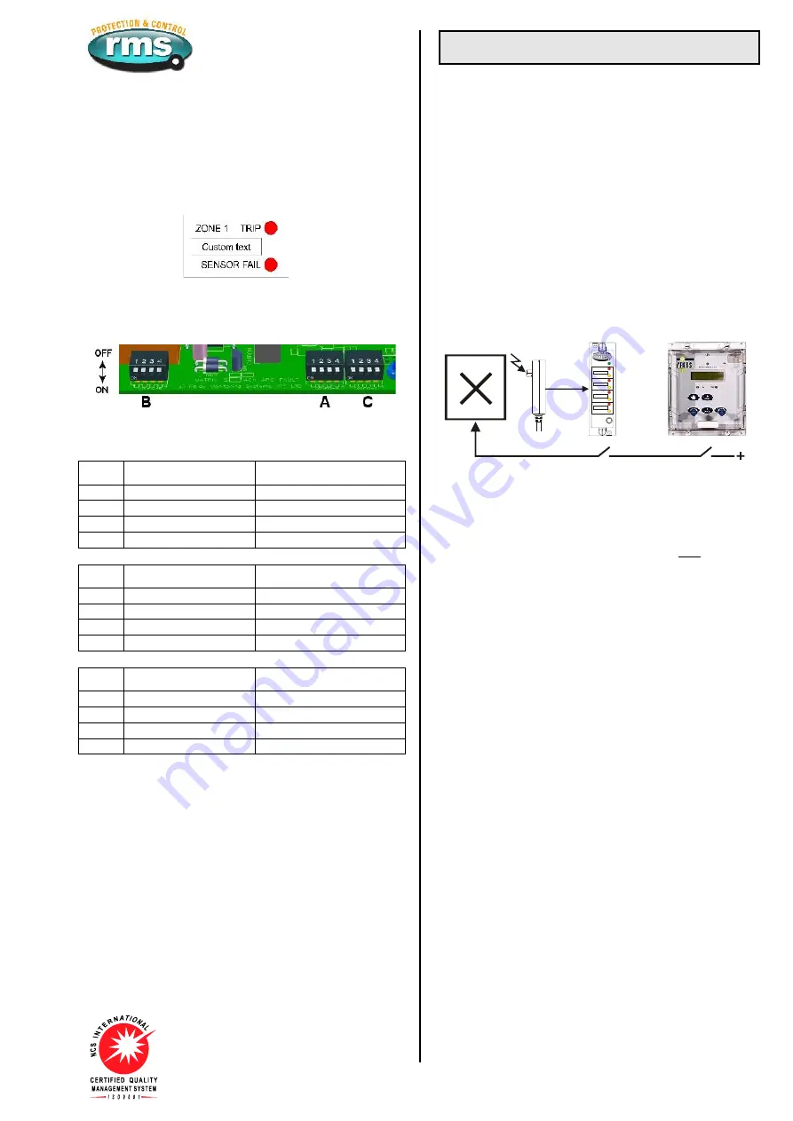
OPERATION INDICATOR
Two (2) LED’s are provided for each tripping zone to provide the
following status indications:
Trip: Flashes for 2s on detection of arc fault in zone & then solid
Resets when front panel reset button pressed or voltage
pulse applied to remote status input.
Fail: Flashes to indicate failure of 1S30 Arc Fault Sensor in zone.
CONFIGURATION SWITCHES
Three banks (A, B & C), of four (4) configuration switches are
accessible to the user by first withdrawing the relay module from
the outer case.
CONFIGURATION SWITCH SETTINGS
The internal wiring label identifies the position of the following
switch functions as follows:
Switch
ON
OFF
A1
Zone 1 Arc sensor fitted
Zone 1 Arc sensor not fitted
A2
Zone 2 Arc sensor fitted
Zone 2 Arc sensor not fitted
A3
Zone 3 Arc sensor fitted
Zone 3 Arc sensor not fitted
A4
Zone 4 Arc sensor fitted
Zone 4 Arc sensor not fitted
Switch
ON
OFF
B1
Zone 1 – 2 Arc sensors
Zone 1 – 1 Arc sensor
B2
Zone 2 – 2 Arc sensors
Zone 2 – 1 Arc sensor
B3
Zone 3 – 2 Arc sensors
Zone 3 -1 Arc sensor
B4
Zone 4 – 2 Arc sensors
Zone 4 – 1 Arc sensor
Switch
ON
OFF
C1
Latching trip contacts
Self reset trip contacts
C2
Independent trip outputs
Common trip outputs
C3
Apply volts to BLOCK
Remove volts to BLOCK
C4
DC only status inputs
AC/DC status inputs
ARC SENSOR CIRCUIT SUPERVISION
The 1S30 Arc Sensor is the heart of the system & supervision of
circuit continuity is critical for correct operation. To monitor the
integrity of the wiring between the 1S30 arc sensor & 1S25 Arc
Monitor, a continuous 2mA supervision current flows between the
units.
The 1S25 alarm contact will drop out after a 1s time delay if it
fails to detect this current.
The failed zone will be indicated by the front panel ‘Sensor fail’
LED.
Operation
ARC SENSOR FUNCTION
The 1S30 is an optical sensor that responds to the flash of light
emitted during the incidence of an arcing fault. Onset of the light
flash & detection by the 1S30 occurs in a few ms.
When an arc is detected, the resistance presented by the 1S30
drops to a level where the current flow increases to approximately
20mA. This increased current flow is instantaneously detected by
the 1S25 & its trip output contacts closed. Refer to the 1S30
Technical Bulletin for further details.
ARC FAULT TRIPPING USING CURRENT CHECK
Fast operation of a tripping scheme usually results in reduced
system security. The arc detection method can however,
combine the 1S25 optical detection technique with a traditional
overcurrent method to maximize system security particularly for
BUS bar protection schemes. Both conditions must coexist for
the trip condition to be met as depicted in figure 8.
ARC FAULT TRIP INITIATE
CB
ARC FAULT
MONITOR
SENSOR
OVER-CURRENT RELAY
3 Pole OC + EF
HEALTHY
ZONE 2
ZONE 3
ZONE 4
ZONE 1
Custom text
Custom text
Custom text
Custom text
FAIL
FAIL
FAIL
FAIL
TRIP
TRIP
TRIP
TRIP
RESET
/TEST
Figure 8:
Key components required to implement an Arc Fault Protection
scheme with an overcurrent check stage
to enhance system security
The application examples in figures 1 to 5 utilize this concept for
enhanced system security in that both the 1S25 AND the OC 50
starter contact must be picked up for a CB trip signal to be
initiated. As the arc fault trip contact picks up considerably faster
than the overcurrent relay starter element, the CB trip time will be
dictated by the overcurrent relay performance.
LOW CURRENT ARCING FAULTS
Arcing faults can occur at low current levels & it is possible for
the over-current starter element to be set above this level. To
avoid this problem & obtain very fast clearance (<10ms), of an
arc fault, the 1S25 arc fault trip contact may be wired directly to
the breaker operate coil. It should be noted that this method may
lead to reduced system security.
ARC DETECTION RESET TIME
(Effect of multiple arc trips)
A delay of 2s is required to reset the 1S25 after an initial arc
sensor trip. Subsequent arc detection will cause the trip output
contacts to re-operate.
INDEPENDENT TRIP OUTPUT CONTACTS
The 1S25 provides up to four (4) tripping zones each with an
independent tripping output. Alternatively configuration switch C2
can be set to OFF so that all trip outputs will operate in the event
of an arc being detected by any sensor.
ARC SENSOR CONTINUOSLY PICKED UP
High ambient light levels may cause a 1S30 to be continuously
picked up. This condition could occur for example if the CB cable
box cover was left open in very high ambient light level
conditions. A non arc fault over-current pick up would then result
in an arc fault trip operation.
To avoid possible mal operation due to this condition, the 1S25 is
designed to automatically disable the arc fault tripping function if
the 1S30 sensor is picked up for >10s. The 1S25 alarm contact
will be set & the front sensor fail LED will flash until the ambient
light level problem is corrected. The 1S25 will then perform an
arc sensor test function & automatically reset.
The failed zone will be indicated by the front panel ‘Sensor fail’
LED.


