Visit
www.rmspl.com.au
for the latest product information.
Due to RMS continuous product improvement policy this information is subject to change without notice. 1S25/Issue F/07/03/2011 - 7/9
Wiring
TERMINATION SCREWS
M4 Screws
An M4 screw kit is supplied as standard with each 1S25.
Additional M4 screw kits may be purchased separately.
1
24
5
26
28
3
Vx
Power supply,
CPU & sensor
fail alarm
Remote reset
Arc fault BLOCK input
Configuration switches
(Primary PCB)
7
9
11
13
15
17
19
21
Zone 1
Arc sensor input
1S30
Arc Fault Sensors
Zone 2
Arc sensor input
Zone 3
Arc sensor input
Zone 4
Arc sensor input
6
8
Zone 1 Trip
Zone 1 Trip
Zone 2 Trip
Zone 2 Trip
4
Common Trip
Switch 1
Switch 2
Switch 3
Switch 4
BANK
A
BANK
B
BANK
C
27
25
23
Fail
Healthy
Alarm common
Signal processing
and logic
functions
ON
ON
ON
Arc sensor fault signal
Zone 3 Trip
Zone 3 Trip
Zone 4 Trip
Zone 4 Trip
12
10
16
14
20
18
22
Common
2
Case & module
earth connection
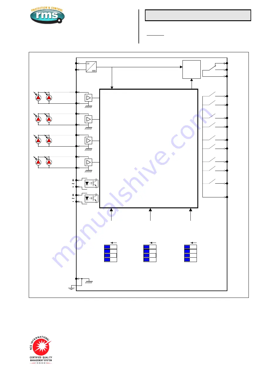
Figure 9: Wiring diagram for 1S25 four zone arc fault monitor - Relays shown in de-energized condition


