


Visit
www.rmspl.com.au
for the latest product information.
Due to RMS continuous product improvement policy this information is subject to change without notice. 1S25/Issue F/07/03/2011 - 9/9
ALARM TEXT LABELS
The 1S25 front panel has provision for custom text to identify the
sensor location for each arc fault tripping zone. The required text
may be engraved on the front panel by the factory if specified at
time of order. Alternatively the front panel may be removed for
engraving by the user or contractor. The RMS web site provides
an ACAD file for this purpose.
The front panel is fabricated from flexible plastic sheet with a
white surface & black substrate to provide high contrast black
text when engraved.
Removal of the front label is achieved by drawing out the 1S25
module from the outer case & pulling the label from the edges at
the mid point between the top & bottom draw out handles. This
will cause the label to bend & disengage from the top & bottom
handle retention points. Once free from the 1S25 module the
front label can be placed on an engraving table. Additional factory
engraved labels may be sourced from RMS for later field
installation.
While an engraved label provides the most permanent record
other methods such as laser printed stick on labels or indelible
marker pen may be satisfactorily employed.
CUSTOM ENGRAVED TEXT DEFINITION
Complete the following tables with one character per box. Refer
to the front panel layout depicted in figure 10. Submit completed
labeling information with the 1S25 product ordering code. For
maximum font size limit text for each alarm point to 1 line x 10
characters.
Text will be left justified.
Zone 1
Zone 2
Zone 3
Zone 4
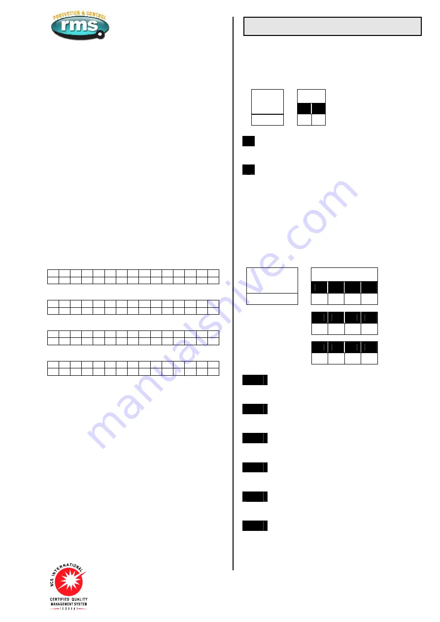
Ordering Information
ORDER CODE
The order code determines the production build in the factory &
cannot be changed in the field.
Generate the required order code as follows: e.g. 1S25 BA
Order
Code
General
Type
1
2
1S25
-
1
AUXILIARY SUPPLY RANGE
A
20 - 70V DC
B
40 - 300V DC & 40 – 275V AC
2
CUSTOM ENGRAVED TEXT
A
Not required No engraving - factory default
B
Required
Complete the custom text details at left
CONFIGURATION CODE
(Optional specification)
The configuration code can be set in the field by withdrawing the
relay module & following the instructions on the side plate label.
The configuration code may be specified at time of order so that
the relay will be shipped from the factory pre-set to meet
customer requirements. e.g. CONFIG-0101-0101-1111
If a configuration code is not specified the factory default will be
set as indicated below. i.e. CONFIG-1111-1111-1111
Configuration
Switches
Specify
Factory
Configuration
A1
A2
A3
A4
CONFIG
-
B1
B2
B3
B4
-
C1
C2
C3
C4
-
A1-4
ZONE 1 - 4 SENSOR INPUTS
1
ON
Arc sensor(s) connected
(Default)
0
OFF No sensor connected
B1-4
ZONE 1 - 4 SECOND SENSOR
1
ON
Second sensor connected
(Default)
0
OFF Single sensor only
C1
OUTPUT CONTACTS FUNCTION
1
ON
Latching
(Default)
0
OFF Self reset
C2
OUTPUT CONTACTS GROUPING
1
ON
Segregated zone tripping outputs
(Default)
0
OFF Common outputs
C3
ARC FAULT INITIATE INPUT FUNCTION
1
ON
Apply volts to BLOCK arc detection
(Default)
0
OFF Remove volts to BLOCK arc detection
C4
STATUS INPUT AC REJECTION
1
ON
DC operation only - AC rejection ON
(Default)
0
OFF AC / DC operation - AC rejection OFF


