background image

Visit  

www.rmspl.com.au


  for the latest product information. 

Due to RMS continuous product improvement policy this information is subject to change without notice.  4M300/Issue K 10/08/21 - 1/6


Features 


 Colour coded 

‘finger safe’ test 

sockets suit standard or 
shrouded type 4mm banana 
plugs 

 14 independent circuits suitable 

for CT or VT connections 

 Test plug available with 

automatic CT shorting option 

 Test plug fitted with insertion 

handles & locking screws 

 Side label instructions on 

changing from normal service 
condition to the test condition  

 Optional automatic DC auxiliary 

isolation function 

 High current / voltage rating 

 Compact & economic design 

 Made in Australia 


Application 


Test  links  are  an  important  accessory  for 
protection,  metering  &  control  panels. 
They  enable  test  technicians  to  quickly  & 
safely isolate protection relays so that test 
signals  may  be  injected  &  system 
performance verified. 

 
There  are  a  number  of  advantages  in 
performing injection tests at the protection 
relay panel: 
 

 Reduction in down time of the 

equipment under test. 

 Testing does not cause 

disturbance to wiring, terminals 
or equipment settings. 

 Existing auxiliary supply to the 

equipment under test may be 
isolated. 

 
The  4M300  Test  Link  Panel  has  been 
designed as a general-purpose isolation & 
test  signal  injection  point.  Standard  4mm 
diameter  sockets  are  employed  so  that 
common  banana  plugs  may  be  used  to 
short CT inputs & connect test equipment.  

 
Equipment  under  test  need  only  be 
removed  for  servicing  if  problems  are 
detected.  


Technical Bulletin                                                                                           

4M300 

Test Block System 


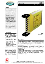
Figure 1: 

4M320-A Test Plug 


Description 


       Made in Australia


The 

Test Block

 type 4M300 comprises fourteen (14) test circuits, each of which is connected 

to  a  separate  pair  of  terminals  at  the  rear  of  the  case.  During  the  normal  operation  of  the 
associated  protection  equipment, each  pair  of terminals  are connected together  by  a circuit-
shorting  link.  Changing  the  4M300  Test  Block  from  the  normal  service  condition  to  the  test 
condition is described below & depicted in figure 3: 


Test Circuit Access 

Access to the circuits, for testing purposes, is gained by first removing the front cover. For the 
4M300-B  model  the 

Isolation  Plug

  is  withdrawn  &  the  circuit  between  terminals  13  &  14 

interrupted.  By  routing  the  main  DC  supply  to  the  protection  scheme  or  relay  through  this 
circuit, removal of the Isolation Plug will thereby prevent inadvertent tripping of the protection 
during the ensuing tests.  


Test Plug Insertion 

Insertion of the 

Test Plug

 type 4M320, isolates the live side circuits from the equipment side. 

The  Test  Plug  carries  28  4mm 

‘finger  safe’  test  sockets.  These  sockets  are  suitable  for 

shrouded or standard 4mm banana plugs. Each test socket is identified by a number, which 
corresponds to the numbered terminal on the rear of the case when the Test Plug is inserted. 
The test socks are colour coded - BLACK to indentify the equipment side sockets & YELLOW 
to identify the live side sockets. 


Summary of Contents for 4M300

Page 1: ...may be used to short CT inputs connect test equipment Equipment under test need only be removed for servicing if problems are detected Technical Bulletin 4M300 Test Block System Figure 1 4M320 A Test Plug Description Made in Australia The Test Block type 4M300 comprises fourteen 14 test circuits each of which is connected to a separate pair of terminals at the rear of the case During the normal op...

Page 2: ...om the protection relay or scheme thereby avoiding dangerously high voltages The continuity of the shorting plug wire links their state of insulation should be checked prior to into the 4M300 test block CT SHORTING AUTOMATIC Internal The 4M320 may be ordered with internal CT shorting links fitted to pre designated positions as follows 4M320 B Internal links between terminals 21 23 25 27 Refer figu...

Page 3: ...orting engaged Circuit isolating bar engaged Equipment side circuits isolated from live side circuits WITHDRAW DC AUXILIARY ISOLATION PLUG 4M300 B model only DC auxiliary supply link between terminals 13 14 is removed Step 1 DC AUXILIARY SUPPLY ISOLATION Step 2 AUTOMATIC CT SHORTING Step 3 CIRCUIT ISOLATION Auxiliary supply isolated 4M300 B CT shorting links engaged INSERT 4M320 B TEST PLUG Automa...

Page 4: ...on TEST LEAD PLUGS Two types of shrouded plug are employed on each test lead as depicted in figure 4 5 Single Plug The single plug is the most compact may be plugged into any test socket Dual Plug The dual or piggy back plug is larger should be plugged into the test sockets on the outside edge of the 4M320 The lead emerging from the dual plug should face out from center of the 4M430 to ensure adeq...

Page 5: ...4M320 TEST PLUG 28 test sockets suitable for 4mm banana plugs Securing screws to retain the Test Plug during testing operations CURRENT RATINGS All CT circuits terminals 20A continuous Terminal 1 to 28 400A 1s VOLTAGE RATINGS All circuits terminals 600V AC continuous 320V DC continuous System auxiliary voltage 40V DC minimum CASE TYPE 2M28 Size 2 28 terminals COMPLIANCE STANDARDS IEC 60068 2 1 600...

Page 6: ...NGTH Match to 4M300 case length A Short Default B Long TYICAL APPLICATION OF 4M300 TEST BLOCK 4M320 TEST PLUG 4M300 Test Block REAR VIEW Live side sockets YELLOW BLACK Equipment side sockets Apply secondary injection test signals Trip alarm contacts or VT connections as required Relay scheme DC auxiliary Protection scheme 1 3 5 7 9 11 13 15 17 19 21 23 25 27 2 4 6 8 10 12 14 16 18 20 22 24 26 28 S...

Reviews: