background image

Rhein-Nadel Automation GmbH


16  

VT-BA-ESK2002_EN-2020 / 06.05.2020 SJ 

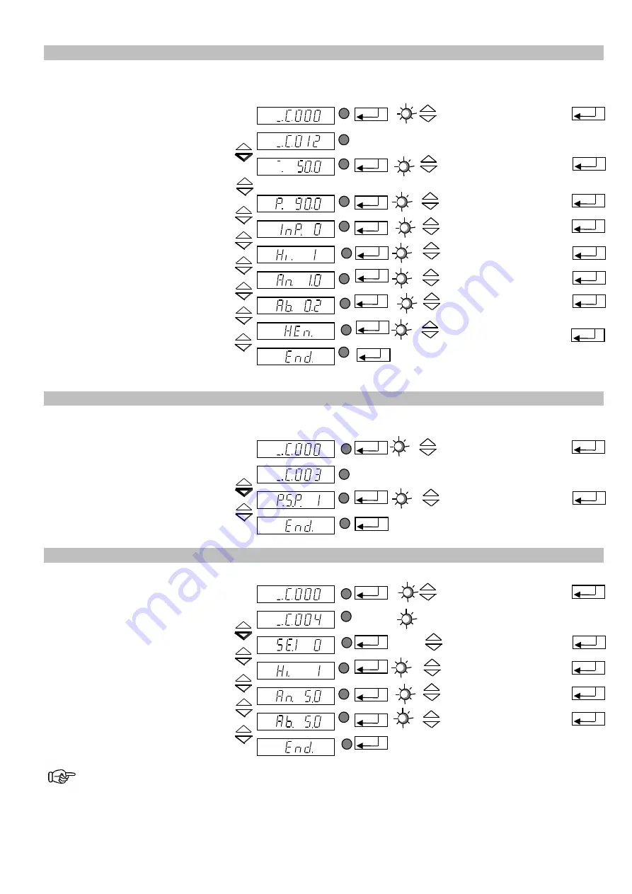
5.5.3.  Code C012 for channel 3, (feed rate output 3, vibratory or conveyor drive) 

Objective: 

Setting


and limiting the vibration amplitude, external enabling, soft start delay and soft stop delay, and the 

vibratory or belt feeder function. 
 

Select code


Set code 


Code C002


Set vibrating amplitude 

Only in controller mode


0 - 100 %  


Limit vibrating amplitude 


50 - 100 % (*) 


External enabling 


I = active 
0 = not active 


External enabling signal direction


I = Start = 24V DC 
0 = Stop = 24V DC 


Soft start delay 


0 - 5 sec. 


Soft stop delay 


0 - 5 sec. 


Switching to vibratory or belt feeder


0 = vibratory drive 
1 = belt feeder           


Return


Save and return to 
main menu 


(*) For RNA feeders with 200 V magnets = 90 %


5.5.4.  Code C003 Seal setpoint 

Objective: 

Sealing-in


the setpoints in the main menu. A direct change of the values is no longer possible. You can 

only make any changes now through code C001, code C002 and code C012. 

Select code


Set code 


Code C003


Setpoint (vibrating amplitude)


1 = adjustable 
0 = input inhibited 


Return


Save and return to 
main menu 


5.5.5.  Code C004 sensor input 1 and code C005 sensor input 2 

Objective: 

Activating and setting the sensor inputs  

Select code


Set code 


Code C004


Sensor 1 input


I = active 
0 = not active 


Invert input signal direction


I = Start = 24V DC 
0 = Stop = 24V DC 


Delay of sensor status  
CLEAR, 

Start delay.


0 - 60 sec. 


Delay of sensor status  
OPERATED, 

Stop delay.


0 - 60 sec. 


Return


Save and return to 
main menu 


Same applies analogously to code 

C005

 (sensor input 2). 


KANAL l
KANAL 2

CODE


KANAL l  
KANAL 2  

CODE 

KANAL l
KANAL 2

CODE

KANAL l
KANAL 2

CODE

KANAL l
KANAL 2

CODE

KANAL l
KANAL 2

CODE

KANAL l
KANAL 2

CODE

KANAL l
KANAL 2

CODE


KANAL l  
KANAL 2  

CODE 

KANAL l
KANAL 2

CODE

KANAL l
KANAL 2

CODE

KANAL l
KANAL 2

CODE

KANAL l
KANAL 2

CODE

KANAL l
KANAL 2

CODE

KANAL l
KANAL 2

CODE

KANAL l
KANAL 2

CODE

KANAL l
KANAL 2

CODE

KANAL l
KANAL 2

CODE

KANAL l
KANAL 2

CODE

KANAL l
KANAL 2

CODE

KANAL l
KANAL 2

CODE

Summary of Contents for ESK 2002

Page 1: ...Operating Instructions Controller for Vibratory Drive Systems ESK 2002...

Page 2: ...relays 11 5 Operation 12 5 1 General 12 5 2 Starting up the controller 13 5 3 Main menu Setpoint entry and display for channels 1 2 and 3 13 5 4 Description of individual codes for controller programm...

Page 3: ...4 35 EU and Electromagnetic Compatibility Directive 2014 30 EU We hereby declare that the product meets the following requirements Low Voltage Directive 2014 35 EC Electromagnetic Compatibility Direct...

Page 4: ...Only qualified professionals are allowed to work on or with the product IEC 60364 or CENELEC HD 384 define the qualification of these persons They are familiar with set up installation commissioning...

Page 5: ...ain even if all directives have been observed and protective measures taken Such residual hazards must be considered by the user in the risk assessment of his machine equipment Non observance may lead...

Page 6: ...type ESK 2002 16 for a total current of 16 A The unit offers the following characteristic features Three power outputs o Channel 1 bowl feeder max 10A variable o Channel 2 linear feeder max 4A variabl...

Page 7: ...or inputs 2 3 enabling inputs 24V DC 10 24VDC Sensor supply 24V DC max 60 mA per sensor input Sensor ON delay 0 60 sec separately adjustable Sensor OFF delay 0 60 sec separately adjustable Outputs 2 r...

Page 8: ...tion Attention Set the controller to minimum output before switching on for commissioning or start up after repairs or replacement of controllers vibratory drives Then watch proper operation while the...

Page 9: ...ive connector Where frequency controllers with selectable output frequency are used an EMC metal gland and a shielded cable are provided 4 3 Sensor inputs and sensor linkages The controller has two se...

Page 10: ...connect sensors of type NPN or PNP Proximity switch general NPN output Proximity switch general PNP output Sensor 2 Proximity switch general NPN output Sensor 1 Proximity switch general PNP output Con...

Page 11: ...hed on by its power switch closed The status output ACTIVE requires the same conditions for switching through as READY In addition the channel must be energized the transistor blocks in case of ACCUMU...

Page 12: ...ptocoupler outputs and external enabling inputs The controller display membrane keypad On Off Pressing this button switches off all connected devices The display shows OFF The controller remains ready...

Page 13: ...on of codes see under 4 4 Setpoint entry for channel 1 bowl feeder Entry in return to display mode for saving Setpoint entry for channel 2 Linear feeder or belt hopper with AC motor not available with...

Page 14: ...gnal direction Start delay Stop delay Setting the sensor input 2 This is the sub menu for activation of sensor input 2 In addition you can set the following functions Invert input signal direction Sta...

Page 15: ...and the vibratory or belt feeder function Select code Set code Code C002 Set vibrating amplitude Only in controller mode 0 100 Limit vibrating amplitude 50 100 External enabling I active 0 not active...

Page 16: ...ake any changes now through code C001 code C002 and code C012 Select code Set code Code C003 Setpoint vibrating amplitude 1 adjustable 0 input inhibited Return Save and return to main menu 5 5 5 Code...

Page 17: ...ack 2 still clear Track 2 sensor 2 full Blow off track 2 relay K2 Track 1 still clear Track 1 Track 2 full Bowl feeder channel 1 Stop about 4 sec later blowing air stop AND logic of the two sensor inp...

Page 18: ...active 0 not active Monitoring depending on Channel 2 I active 0 not active Time till alarm comes up 3 240 sec Switching off channel 1 and channel 2 I see below 0 see below Switch relay K1 I Alarm on...

Page 19: ...eturn Save and return to main menu Under menu item HA half wave you can check whether the operating mode 100 50 Hz is selected correctly 5 5 9 Code C200 Inhibiting all code entries Objective An accide...

Page 20: ...o default values or retrieving stored application specific settings Select code Set code Code C210 Default setting Application specific parameters Return Save and return to main menu FAC Select and ac...

Page 21: ...Rhein Nadel Automation GmbH 21 VT BA ESK2002_EN 2020 06 05 2020 SJ 6 Dimensioned drawing...

Page 22: ...feeder Capacitor motor Sensor 1 accu mulation Vibratory feeder 230V 50 60Hz supply connection M 2A Controller m c b Wire jumper not required for 50 60Hz required for 100 120Hz Wire jumper not require...

Page 23: ...ngenstr 96 CH 3360 Herzogenbuchsee Switzerland Tel 41 0 62 956 10 00 Fax 41 0 62 956 10 10 E Mail info handling systems ch www handling systems ch Manufacturing and Sales Pol Ind Famades c Energia 23...

Reviews: