Rhein - Nadel Automation GmbH
9
Date: 14.04.2014
VT-BA-GL-GB
Adjustment of the linear feeder type GL 1:
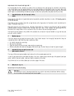
For the adjustment of the oscillator in parallel to the counter-mass four leaf springs are included in the delivery.
These leaf springs must be inserted between the spring assemblies and the distance cams (one each above and
below). After that the spring fastening screws must be tightened with the specified tightening torque (see "technical
data" chapter 1). Before starting the distance springs must be removed and the side plates must be mounted.
6
Specifications for the design of the
track
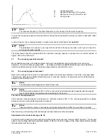
The projection of the track in longitudinal direction towards the oscillator should be at a ratio of
1/3 feeding side to
2/3 discharge side.
The tracks must be of solid construction. upright beams with a high moment of resistance are to be preferred (U-
beams, rectangular tubes, etc.).
Especially tracks for thin material as eg. stamped metal parts, etc. should be manufactured with the greatest
possible clearance between material to be conveyed and cover. Here it must, however, be guaranteed that the
material to be conveyed does not run one piece on top of the other or becomes wedged together.
The track should be located in the middle of the oscillator. By no means it may be installed in a way that one side
projects over the oscillator.
7
Maintenance
The linear feeders are generally maintenance-free. They should, however, be thoroughly cleaned when they are
considerably dirty or after fluids have been spilled over them.
For that first unplug the mains plug.
Remove the side plates.
Clean the inside of the linear feeder, especially the magnetic gap.
After mounting the side plates and plugging in the mains plug, the linear feeder is ready for operation again.
8.
Stockkeeping of spare parts and
after-sales service.
The range of the spare parts available may be taken from the separate spare parts list.
In order to guarantee quick and faultless handling of the order, please always state the type of equipment (see type
plate), number of pieces needed, spare part name and spare part number.
You will find a list of our service addresses on the back page of the cover
9
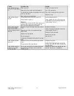
What is to do, if...
Instructions for trouble-shooting
Attention
The control unit or the connecting terminal box may only be opened by an electrician. Before opening
the a.m. devices, the mains plug must be unplugged!


