background image

ALIGNMENT PROCEDURES

MODEL:

HIF-6880USMPT


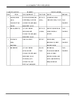
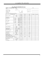
 FM  AND  AM  RF  ALIGNMENT  CHART ( IF )

Date:

Step

item

Input Circuit

Output Circuit

Tuner

Adj -

Adjustment

Setup

Setup

setting

Point

     Unless otherwise specified set switches as follows:

     FM           Function:  FM

     Adjust generator frequency to a center of the FM band where no FM broadcast exists

IF

Connect FM IF

Connect Co19 and GND

FM in band


Adjust for straight and

1

Adjustment

sweep output

 IF-OUT terminal to

end

T304

symmetrical S-curve

terminal to IC302

 IF sweep input terminal

with max.amplitude.

2

FM

Headphone jack or 

 87.5 MHz

L303

Adjust L301 for max output

Band setup

speaker terminal

108MHz

Done

FM SG ANT.

Headphone jack or 

90.1 MHZ

L302

Adjust for max.output and

3

Tracking (1)

Terminal 90.1 MHz,

speaker terminal

MONO

best waveform

1kHz, +-22.5kHz dev

4

Tracking (2)

106.1 MHz, 1 kHz

Headphone jack or 

106.1 MHz

CT303 Same as above.

 +-22.5 MHz dev

speaker terminal

5

Repeat steps 3 and 4.

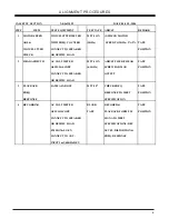
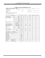
MW

IF

Connect standard loop

Connect input terminal 

MW in band


Adjust tor max. amplitude

1

Adjustment

antenna to output ter-

genescope to detector 

end

T302

with symmetrical 450 kHz.

minal of genescope

output

2

MW

Headphone jack or 

522 kHz

T301

Adjust L135 for max output

Band

speaker terminal

1620 kHz

CT302 Adjust CT133  for max output

3

Tracking (1)

612 kHz  400 kHz,

Headphone jack or 

612 kHz

T303

Adjust for max.output and

3% mod

speaker terminal

best waveform

4

Tracking (2)

1404 kHz  400 kHz,

Headphone jack or 

1404 kHz

CT301   Same as above.

3% mod

speaker terminal

5

Repeat steps 3 and 4.


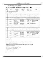
 TAPE  SECTION

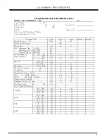
HEAD ADJUSTMENT  (AZIMUTH)

10 kHz test tape (example:MTT-114N) must be used for this adjustment. Connect to VTVM or oscilloscope to the head-

phone  JCK or speaker terminal Press the play button.

Adjust the azimuth by using a screw driver to maintain the maximum L & R output voltage. Adjust tape. Please secure the

azimuth position by using locking paint.

RECODING BIAS OSCILLATOR FREQUENCY ADJUSTMENT

Connect the frequency counter to of R601 two ends.

Press REC button of tape .

Adjust T201 obtain 60 kHz  +-100 HZ

7

Summary of Contents for HIF-6880USMPT

Page 1: ...HIF 6880USMPT...

Page 2: ...ICATIONS CONTENTS AM FM TUNER SECTION DISASSEMBLY INSTRUCTIONS 3 ADJUSTMENT LOCATIONS 4 ALIGNMENT PROCEDURES 5 12 IC BLOCK DIAGRAMS 16 20 VOLTAGE CHARTS 13 15 BLOCK DIAGRAM 21 WIRING DIAGRAM 22 PRINTE...

Page 3: ...tive maton the floorand desk andwear a wrist band connected to groundthrough a 1Mohm resistor to protect the laserdiode from staticdamage If thelens should get dusty blow off thedust carefully fromthe...

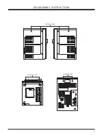
Page 4: ...DISASSEMBLY INSTRUCTIONS MODEL NE 562 3 SCREW3X10PA SCREW3X10PA SCREW3X10PA...

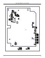
Page 5: ...ADJUSTMENT LOCATIONS 4...

Page 6: ...HEAD AZIMUTH AC VOLT METER MTT 113N ADJUST THE R P HEAD TAPE OSCILLOSCOPE 6 3KHz SCREW FOR MAX POSITION CONNECT TO SPEAKER OUTPUT OR DUMMY LOAD 3 PLAYBACK SAME AS ABOVE MTT 257 CHECK FREQ TAPE FREQ R...

Page 7: ...HEAD AZIMUTH AC VOLT METER MTT 113N ADJUST THE R P HEAD TAPE OSCILLOSCOPE 6 3KHz SCREW FOR MAX POSITION CONNECT TO SPEAKER OUTPUT OR DUMMY LOAD 3 PLAYBACK SAME AS ABOVE MTT 257 CHECK FREQ TAPE FREQ RE...

Page 8: ...s 3 and 4 MW IF Connect standard loop Connect input terminal MW in band Adjust tor max amplitude 1 Adjustment antenna to output ter genescope to detector end T302 with symmetrical 450 kHz minal of gen...

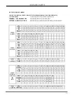
Page 9: ...Locked 90 1 MHz db 26 32 Sensitivity 98 1 MHz db 26 32 106 1 MHz db 26 32 ACA 300 KHz db 20 15 2 Signal 300 KHz db 20 15 Image Rejection AT 106 1 MHz db 22 16 IF Rejection AT 90 1 MHz db 50 40 3db Lim...

Page 10: ...B M 60 66 1404 KHz dB M 60 66 Auto Locked 612 KHz dB M 66 70 Sensitivity 999 KHz dB M 66 70 1404 KHz dB M 66 70 S N 5mv M dB 35 30 ACA 9 KHz dB 18 12 9 KHz dB 18 12 Band Width 6dB Side KHz 3 10 Side K...

Page 11: ...at 1 KHz dB 0 0 at 10 KHz dB 3 6 at KHz dB P B S N 1K odB DC Opetation dB AC Optetaion dB 45 40 Min Vol Hum Noise AC Optetaion mv 1 3 Max Vol Hum Noise AC Optetaion mv 20 30 10 THD Output 1KHz odB RM...

Page 12: ...b at 90 Sec Recovery time for 20db at 90 Sec R P Frep Response at 100 Hz dB 3 6 REC CD 20dB at 1 KHz dB 0 3 at 10 KHz dB 3 6 R P S N Built Mic dB FM 1mv in dB 38 33 R P THD at 10dB 1KHz 5 10 R P Chann...

Page 13: ...C Opetation dB AC Optetaion dB 55 50 Hum Noise Min Vol mv 2 3 AC Optetaion Max Vol mv 5 8 10 THD Output RMS mw 4500 4000 THD 20dB at 1 KHz 1 3 Channel Separation R L dB 40 30 YEDS 0dB L R dB 40 30 Cha...

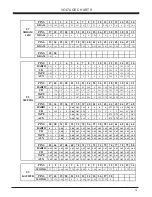
Page 14: ...0 0 22 FM 2 19 0 0 0 2 3 3 64 3 9 0 02 0 0 02 4 45 0 0 0 0 3 2 18 IC301 FM ST 2 2 0 0 0 2 3 3 64 3 79 3 79 0 0 02 4 45 0 0 0 0 2 2 18 LC72131 PINS 17 18 19 20 21 22 AM 4 5 0 82 0 82 3 1 0 2 3 FM 4 5 0...

Page 15: ...47 48 RADIO 0 0 0 0 2 86 1 81 2 86 0 0 0 0 2 73 2 73 3 4 3 54 2 91 CD 0 2 88 0 0 2 86 1 81 2 86 0 0 2 79 0 0 0 0 06 0 3 2 91 TAPE 0 0 0 0 2 86 1 81 2 86 0 0 0 0 2 73 2 73 0 03 0 7 2 91 AUX 0 0 0 0 2...

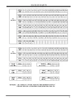
Page 16: ...7 88 89 90 91 92 93 94 95 96 DSP 0 0 1 61 1 7 2 07 0 2 88 0 2 75 1 63 0 0 06 0 0 0 0 PINS 97 98 99 100 DSP 0 0 07 1 69 0 PINS 1 2 3 4 5 6 7 8 9 10 11 12 13 14 15 16 SSP 1 71 1 75 1 69 1 52 1 7 3 38 1...

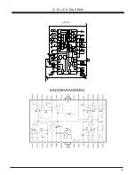
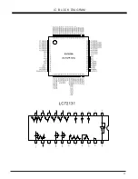
Page 17: ...16 IC BLOCK DIAGRAM MODEL NE 562...

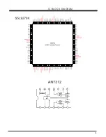
Page 18: ...17 IC BLOCK DIAGRAM MODEL NE 562...

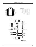
Page 19: ...18 IC BLOCK DIAGRAM MODEL NE 562...

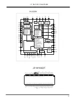
Page 20: ...19 IC BLOCK DIAGRAM MODEL NE 562...

Page 21: ...20 IC BLOCK DIAGRAM MODEL NE 562...

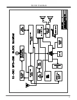
Page 22: ...BLOCK DIAGRAM 21...

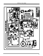
Page 23: ...WIRING DIAGRAM 22...

Page 24: ...SCHEMATIC DIAGRAMS 22 23...

Page 25: ...SCHEMATIC DIAGRAMS 23 24...

Page 26: ...SCHEMATIC DIAGRAMS 24 25...

Page 27: ...SCHEMATIC DIAGRAMS 25 26...

Page 28: ...SCHEMATIC DIAGRAMS 26 27...

Page 29: ...SCHEMATIC DIAGRAMS 27 28...

Page 30: ...SCHEMATIC DIAGRAMS 28 29...

Page 31: ...SCHEMATIC DIAGRAMS 28 30...

Page 32: ...PRINTED CIRCUIT BOARDS 31 173 056320 01 173 056301 09...

Page 33: ...PRINTED CIRCUIT BOARDS 32 173 056320 01...

Page 34: ...PRINTED CIRCUIT BOARDS 33...

Page 35: ...PRINTED CIRCUIT BOARDS 34 173 056351 01 173 056356 01 173 0563 1 09...

Page 36: ...35 EXPLODED VIEW PARTS LIST CABINET MODEL NE 562...

Page 37: ...36 EXPLODED VIEW PARTS LIST CABINET 56 57...

Page 38: ...056205 0101 VOLUME LIGHT BOARD 1 17 199 000002 01 OIL DAMPER 1 18 408 056217 2490 CD OPEN BUTTON 1 S1 203 300200 10 SCREW 3X10 PA 44 19 148 030000 40 LED 3 S2 203 300200 12 SCREW 3X12 PA 7 20 134 0562...

Reviews: