Tips
Conseil
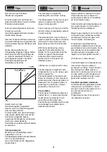
The next step is to adjust the
collective pitch „maximum“ setting.
The ideal situation is that rotor speed
remains constant over the whole
range of collective pitch.
This is necessary for the gyro and the
tail rotor torque compensation system
to work correctly.
The collective pitch curve function is
used to adjust the maximum collective
pitch value to the point where rotor
speed does not fall off at full throttle.
With the model hovering, slowly
advance the throttle towards full-
throttle. If rotor speed falls off as the
throttle is opened, the maximum
collective pitch value should be
reduced until no change can be
detected (curve 1).
[ Pitchkurve = Collective pitch curve ]
The last stage is to adjust tail rotor
compensation, if you are using a gyro
which requires this.
The ideal situation is that the model
shows no tendency to turn around its
vertical axis when the model climbs or
descends. This unwanted rotation is
caused by the variations in torque
produced by the main rotor.
Pre-condition:
The model is trimmed accurately for a
neutral hover, i.e. when hovering the
model shows no tendency to turn
around the vertical (yaw) axis.
The throttle and collective pitch curves
must already be programmed as
described previously.
Régler ensuite le „maximum“ du pas.
Il faut s‘assurer que le régime du
moteur reste constant sur l‘ensemble
de la fourchette du pas.
Cette condition est indispensable pour
que le gyroscope et le rotor arrière
fonctionnement correctement.
Régler le pas maximum en fonction de
la courbe de pas ci-dessous de telle
manière que, lorsque les gaz sont à
fond, le régime ne baisse pas.
En partant de l‘ajustement de la
sustentation, déplacer le manche des
gaz lentement vers plein régime, il faut
ainsi réduire le pas maximal de telle
manière qu‘aucun changement de
régime ne soit perceptible (courbe 1).
[ Pitchkurve = courbe de pas ]
Il faut enfin régler la compensation du
rotor arrière lorsqu’on utilise un
gyroscope qui l’exige. Il faut s‘assurer
que, lorsque le modèle s‘élève ou
descend il ne tende pas à tourner sur
son axe vertical. Cette tendance est
produite par la différence de couple
généré par les pales du rotor.
Condition préalable à satisfaire:
le modèle doit être parfaitement réglé
lorsqu‘il est en sustentation, c‘est-à-
dire qu‘il ne tourne pas autour de son
axe vertical lorsqu‘il est en
sustentation.
Programmer les gaz et le pas selon
les indications fournies.
Tips
Nun wird nun der Pitchwert
“Maximum“ eingestellt.
Erreicht werden soll, daß über den
gesamten Pitchbereich eine konstante
Drehzahl erhalten bleibt.
Dies ist notwendig, damit sowohl die
Kreisel als auch die
Heckrotorausgleichsfunktion optimal
funktionieren können.
Über die Funktion Pitchkurve wird der
maximale Pitchwert so eingestellt, daß
bei maximalem Gas die Drehzahl nicht
abnimmt.
Geben Sie ausgehend vom
Schwebeflug langsam Vollgas. Nimmt
die Drehzahl in Richtung Vollgas ab,
so muß der maximale Pitchwert so
weit abgesenkt werden, bis keine
Drehzahlveränderung mehr
feststellbar ist (Kurve1).
Zuletzt muß noch der
Heckrotorausgleich eingestellt
werden, wenn ein Kreisel eingesetzt
wird, der dies erfordert.
Erreicht werden soll, daß bei Steigen
oder Sinken das Modell nicht um die
Hochachse wegdreht. Dieses
unerwünschte Wegdrehen ist bedingt
durch das unterschiedliche
Drehmoment, welches die Rotorblätter
verursachen.
Voraussetzung ist:
Modell ist im Schwebeflug neutral
ausgetrimmt, d.h. im
Schwebeflugzustand dreht das Modell
nicht um die Hochachse.
Gas- und Pitchkurve wie angegeben
programmiert.
61
Pitchkurve
0%
100%
1
linear
Summary of Contents for Moskito Sport II
Page 1: ...S 2884 II ...
Page 8: ...Baustufe Stage Stade 1 8 II S1393 ...
Page 10: ...Baustufe Stage Stade 1 10 II ...
Page 12: ...Baustufe Stage Stade 1 12 II ...
Page 14: ...Baustufe Stage Stade 2 14 II ...
Page 16: ...Baustufe Stage Stade 3 16 II ...
Page 18: ...Baustufe Stage Stade 4 18 II ...
Page 20: ...Baustufe Stage Stade 4 5 20 II ...
Page 22: ...Baustufe Stage Stade 6 22 II ...
Page 26: ...Baustufe Stage Stade 7 26 II ...
Page 28: ...Baustufe Stage Stade 7 8 28 II ...
Page 30: ...Baustufe Stage Stade 8 9 30 II ...
Page 32: ...Baustufe Stage Stade 10 32 II ...
Page 34: ...Baustufe Stage Stade 10 34 II ...
Page 36: ...Baustufe Stage Stade 11 12 36 II ...
Page 38: ...Baustufe Stage Stade 12 38 II S4536 ...
Page 40: ...Baustufe Stage Stade 12 40 II ...
Page 42: ...Baustufe Stage Stade 12 42 II ...
Page 46: ...Baustufe Stage Stade 14 46 6 4 1 2 3 5 7 8 9 11 mm 14 0 II S3879 ...
Page 48: ...48 Baustufe Stage Stade 14 P E N C G C G C G TAPE A 14 2 14 1 II ...
Page 50: ...50 Baustufe Stage Stade 15 15 A II ...
Page 56: ...56 Baustufe Stage Stade 15 HB Re 9 0 HA Li Re 15 3 HA 11 mm HB 20 mm II ...

