ENGLISH
9
Instructions and User Manual
We recommend replacing the brass stuffing tube if you replace the drive shaft or if you notice wear or vibration in
the drive line.
1.
Follow
Servicing the Drive Shaft
Steps 1–9.
2.
Use a 2.5mm hex driver to remove both screws from the motor mount.
3.
Disconnect the motor wires and remove the motor from the hull, placing the motor aside.
4.
Using a 2mm L-shaped hex driver, loosen the jet pump housing bolt until it is even with the nut holding it in
place.
Do not remove the bolt completely.
5.
Insert the drive shaft into the brass stuffing tube, applying minimal lateral force while simultaneously
pushing away from yourself.
If water does not stream out of the water outlets while the boat is moving forward, immediately stop the boat and
inspect the water cooling system.
1.
Disassemble and clean the water cooling system to remove blockage and prevent overheating.
2.
Replace any damaged parts.
3.
Inspect the system for loose connections, kinks or tears in the line.
10.
Use Marine Grease to apply 3–5 pumps of grease directly into the brass stuffing tube. Before installing the
drive shaft into the brass tube, place a paper towel between the motor coupler and the brass stuffing tube to
catch excess grease.
11.
Install the drive shaft into the brass tube. Insert the drive shaft into the brass tube using a plunging and
spinning motion thereby coating the drive shaft with grease.
12.
Using the paper towel placed in between the stuffing tube and the motor coupler, push the drive shaft out
of the brass stuffing tube. Ensure you have used enough marine grease. If there is not excess grease, remove
the drive shaft and apply additional grease. Repeat Step 10.
13.
Push the drive shaft into the motor coupler.
14.
Apply a small amount of blue Thread Lock on the set screw. Use a 2mm hex driver to install the set screw into
the motor coupler and tighten the set screw by hand. Tip: Apply marine grease to the tip of your 2mm driver.
The grease will keep the set screw in place.
15.
Ensure the impeller does not touch the jet pump housing by spinning the motor or flywheel by hand. If the
drive shaft and impeller housing are touching, loosen the set screw and pull the drive shaft out just enough
to provide the appropriate amount of clearance.
16.
Install the jet pump nozzle on the hull. Once all the screws are loosely in place, tighten the screws down in a
crisscross pattern. Do not over tighten the screws or you will damage the flange on the jet pump nozzle.
17.
Install the rubber bellows from inside the hull outward. Apply a small amount of marine grease to the bel-
lows to ease their movement through the hull. Remove excess grease after installation.
18.
Apply a small amount of marine grease along the steering and trim links. This allows them to slide into the
rubber bellows. After installation, remove any excess grease.
19.
Attach the ball ends of the steering and trim links to the nozzle mechanics. Set the jet nozzle trim to the stock
setting.
Tip:
Power on your boat so that the steering servo centers before tightening the steering link set screw
found on the steering servo arm.
20.
Reattach the silicone cooling line to the brass fitting on the jet pump housing.
NOTICE:
Running the boat in saltwater could cause some parts to corrode. If you run the boat in saltwater, rinse it tho-
roughly in freshwater after each use and lubricate the drive system. You can also use water displacement spray to
help prevent the parts from corroding.
NOTICE:
Because of its corrosive effects, running RC boats in saltwater is at the discretion of the modeler. Corrosion is not
covered under warranty.
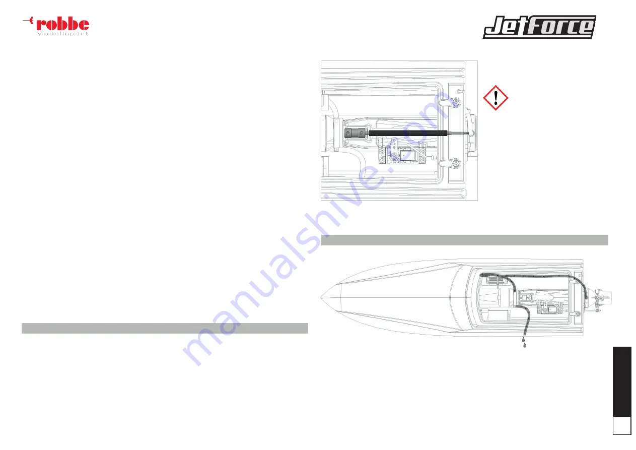
R E P L A C I N G T H E S T U F F I N G T U B E
NOTICE:
Applying too much force prevents the drive shaft
from entering the brass tube correctly.
6.
Install the new brass stuffing tube (from
inside the boat) pushing it toward the back
of the boat. Verify the brass tube sits inside
the jet pump housing support webbing.
NOTICE:
Do not push the brass tube flush with the pump
or you will damage the support webbing.
7.
Follow Servicing the Drive Shaft Steps 10–20
to reassemble the jet pump.
WAT E R CO O L I N G S Y S T E M
WARNING:
Do not allow the drive
shaft to push the brass tube out the
back of the pump. Doing so could
damage the pump webbing.


