Order Number
40 MHz No. F4044
FC-16 Boat `n Truck
16
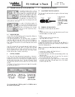
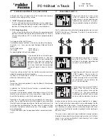
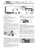
A) Battery Connection
B) Aerial
C) Sockets for controls 1-8 (CH)
D) Sockets for Multi-Switch/ Prop modules (Multi In)
E) Socket for Multi-Switch/ Prop power supply (To Multi OP)
F) Mix switch sockets 1-2 (Mix SW)
G) Crystal socket
H) CAMPac connector socket
I) DSC connector socket for Trainer Module No. F1574
25. OPTION MODULE CONNECTION
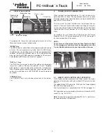
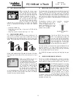
Linear proportional slider:
To install the linear slide controls, the aluminium cover must be
removed from the slider well on the centre front of the Tx case.
Use a sharp knife to lift and remove the cover plates. Fit the slider
from the rear and fix using the supplied screws. Install the new
surround, remove protective film and attach the control knob.
Connection:
The linear proportional slider expands the Tx by one fully propor-
tional control channel. The connection is made in any of the bank
of sockets 1-8 (CH); the servo direction is defined in “REVR” or
by rotating the plug by 180 degrees in the socket.
3-position switch channel:
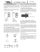
Remove the blind cover to install a switch in any of the two option
wells on the Tx front upper face. Simply prise the blind cover
out with a suitable object. Remove retainer nut from switch, feed
switch into your preferred position from the rear. Fit the retaining
nut. Break out the corresponding blank switch position from the
cover using pointed pliers or tweezers. Switch labels can be fitted
to the recess in the rear of the cover, the cover is then snapped
back into position in Tx case.
Connection:
This switch unit expands one channel to be a 3-position switch
channel with low, middle and high positions. The connection is
made to your choice of channel in the control sockets 1-8, the
servo direction will be adjusted by “REVR” function or simply ro-
tating the plug 180 degrees in the socket.
1 2 3 4 5 6 7 8
Multi-IN
1 2
Mix-SW
Spannungsversorgung
Antenne
CAMPac
Anschluss
To Multi OP
CH
TX
DSC
24. LAYOUT OF TX PCB SOCKETS
A
F
D
E
H
C
B
G
I
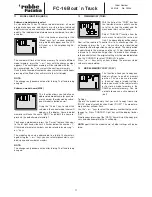
External Mix Switch:
Mix switches switch mixers on and off. Installation is made in op-
tion wells 1 or 2 in the same manner as switch channel switches.
Connection is made to Tx PCB in the MIX-SW (1-2) sockets.
Multi-Switch, Multi-Prop-Module
These modules split one proportional channel into 8 proportional
and/or switched functions. The Multi-Prop-8, Multi-Switch-16 or
a Multi-Switch-Prop-12+2 module can be installed. The resulting
transmitter is ideal for controlling models fitted with many com-
plex auxiliary working systems and features.
Connection:
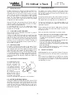
The module is installed in the Tx with the 3-pin socket on the
solder side of the module facing the inside of the Tx (not the
outside edge). The black plug on the single-core lead from the
Multi-Module is connected to the socket marked “Multi In 1.2) on
the main PCB. The white plug (twin core cable) from the Multi-
Module is connected to the socket marked “To MULTI OP”. The
Multi-system will not work until you have programmed channels
7 or 8 (CH 7/8) as a MULTI channel within the MULTI program
menu.
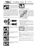
Caution:
if you install and connect a Multi-Module you MUST
NOT connect any other Tx control to channels 7 or 8 (sockets
CH7 + 8).
Battery Connection
CAMPac connector
socket


