background image

Order Number

40 MHz      No. F4044

FC-16 Boat `n Truck

23

Summary of Contents for Futaba FC-16 Boat`n Truck

Page 1: ...Operating Instructions 40 MHz 6 8 1 No F4044 FC 16 Boat n Truck ...

Page 2: ...1 13 Model memory copy COPY 11 14 System adjustments PARA 12 14 1 Submenu modulation type PULS 12 14 2 Submenu model memory reset REST 12 14 3 Submenu stick mode STCK 12 15 MULTI SWITCH NAUT 12 16 Failsafe adjustment F S only in PCM 13 17 Cross mixer XMX 1 2 13 18 V mixer VMX 1 2 14 19 Exponential function EXPO 14 20 Sub Trim SUB TRIM STRM 15 21 Servo Reverse REVR 15 22 Servo end point adjustement...

Page 3: ... part yourself Hidden damage can occur through ingress of water or after a collision this can lead to function failure after a short operation time Only genuine robbe replacement parts or accessories may be used with this equipment Always use genuine robbe Futaba connectors and crystals No modifications may be made to the equipment Routine checks before use If there is more than one modeller opera...

Page 4: ...emory module 1 CONTENTS 1 FC 16 Boat n Truck transmitter 1 R118F FM receiver 1 S3003 servo with accessory bag 2 Linear proportional potentiometer controls 1 Switch harness with charge cable 1 pair of crystals 1 1 RECOMMENDED ACCESSORIES 9 6 V 1500 mAh transmitter battery No 4566 9 6 V 3500 mAh transmitter battery No 4569 4 8 V 2000 mAh receiver battery No 4551 F series transmitter charge lead No 8...

Page 5: ...ery pack 2 3 TECHNICAL DATA FC 16 BOAT N TRUCK TRANSMITTER Frequency 40 MHz Channel spacing 10 kHz Modulation PPM FM PCM 1024 Current consumption 30 200 mA Voltage 9 6V NiMH Dimensions 230 x 200 x 50 mm Weight 1000g with battery 3 R118F RECEIVER The receiver covers a wide spectrum of uses with 8 channels in FM operation Compact in size by use of SMD technology The high quality FET front end and th...

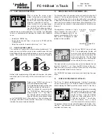
Page 6: ...per month That means after 10 months of inactivity a fully charged battery will be flat even if there is no load on it The transmitter battery can be charged without removal from the transmitter case by using the integrated charging socket located on the right hand side of the case For convenient charging we recommend the robbe Unicharger no 8500 To avoid a short circuit whilst charging always con...

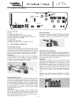
Page 7: ...transmitter and receiver may be operated on varying fre quency channels within the 40 MHz band Matching transmitter and receiver crystals must be fitted to their respective sockets in the transmitter and receiver cases The channel number of both transmitter and receiver crystal must be the same for the system to work To change the transmitter crystal you must open the transmitter case back see sec...

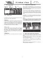
Page 8: ...e socket Channel 1 Steering Channel 2 Channel 4 Linear propor tional chan 5 Linear propor tional chan 6 Throttle Channel 3 B 7 4 SERVO CONNECTION The stick control functions for throttle steering etc are to be found in channels 1 4 Channels 5 and 6 are linear proportional channels with slider potentiometers Channels 7 and 8 may be used either with switches or opera ted with Multi Modules The diagr...

Page 9: ...d to the Trainer socket this allows operation of the receiver and servos without RF transmission from the Tx The robbe Futaba DSC cable No F1422 and the Trainer Module No F1574 are needed for this The Trainer module 4 is connected to the Tx PCB see page 16 DSC operation can only be made with receivers fitted with a DSC socket C e g Rx R 118F Note To avoid the transmitter radiating RF the Tx crysta...

Page 10: ...rTasten Model 1 10 Kan 1 8 Drücken Sie die beiden ModeTasten für ca 2 Sekunden 1 Taste oder für min 0 5sek drücken 1 Data Tasten 1 1 1 Kan 2 8 Kan 2 8 Kan 2 8 10 MENU STRUCTURE Press both mode keys for 2 seconds Mode key Cursor key Data key Chan 1 8 only in PCM M mode Chan 2 8 Chan 2 8 Chan 2 8 ...

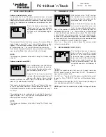
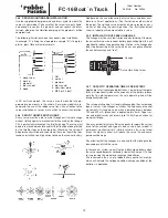
Page 11: ...ted to a total of 4 characters again using the or keys you can select alphanumeric sym bols space and number characters NOTE The changes only become active after turning Tx off and turning on again 12 TRIM MEMORY TRIM With the help of the TRIM function the individual servo neutrals can be set after testing the model and the mechanical trims set to neutral Select TRIM SET function from the main men...

Page 12: ... ase be careful how and when you use the REST function 14 3 SUBMENU STICK MODE STCK This menu allows you to choose the stick control layout to suit you The stick controls 1 4 must always remain in their factory position in the Tx con trols sockets for this software to func tion correctly Select STCK function in PARA menu Select MODE 1 to 4 The changes become active after turning Tx off and turning...

Page 13: ...early fully discharged Operation of the model must cease immediately this warning is given If you need throttle to return the model to you closing the throttle stick and re opening will give throttle control to move it to a safe position for recharging You now have 30 seconds to do this before the battery failsafe re occurs if the voltage situation has not improved The function works also for spee...

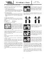
Page 14: ...lue The selected age will appear in the display The adjustment range of EXPO function lies between 100 and 100 The factory default is set to 0 for all controls NOTE Exponential also reduces the trim value by the correspon ding amount therefore a maximum of 50 EXPO should be used 18 V MIXER VMX 1 2 Moving a transmitter control will nor mally move only that servo connected to that channel number If ...

Page 15: ...e end point to be set in each direction for all channels This can be adjusted from 40 140 of the total servo travel including trim This is to avoid stalling that servo against a mechanical limit before it has reached its electronic limit This works on all servo channels and reduces all mixed functions Ple ase note the trim amount is also proportional to the total servo throw set The adjustment is ...

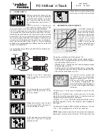
Page 16: ...tion in Tx case Connection This switch unit expands one channel to be a 3 position switch channel with low middle and high positions The connection is made to your choice of channel in the control sockets 1 8 the servo direction will be adjusted by REVR function or simply ro tating the plug 180 degrees in the socket 1 2 3 4 5 6 7 8 Multi IN 1 2 Mix SW Spannungsversorgung Antenne CAMPac Anschluss T...

Page 17: ... proportional channel expansion Occupies only 1 servo channel but can control 8 servos or speed controllers independently of each other Multi Switch 16 Decoder Memory No 8369 For each Multi Switch module in the transmitter you need one de coder at the receiver end This takes up only one servo channel and can switch 16 channels directly Operating voltage 4 8 24 Volts up to 1 8 A per output Multi Sw...

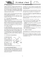
Page 18: ...exits the model feed it through a length of silicon fuel tube to protect the aerial The aerial must be kept well clear of any rotating parts of the drivetrain 26 1 SWITCH HARNESS The Rx switch harness must be operable in both directions with no mechanical limits The opening in the model must be large enough to allow full action of the slide switch With IC powered models the switch should be placed...

Page 19: ...SERVO LINKAGES The linkage must be very low friction and non binding Otherwise the current drain on the receiver battery pack will be high this will significantly reduce the operating time Friction in the linkage also leads to poor centring of the servo which has a negative effect on the control accuracy and feel 26 7 CAPACITY OPERATING TIME OF RX BATTERY Applicable for all rechargeable batteries ...

Page 20: ...or will cause constant interference and loss of control We recommend using the robbe suppresion filter kit No 8306 or the capacitor kit No 4008 Every brushed motor must be individually suppressed as in the illustration 27 4 BATTERY ELECTRONIC IGNITION The increase in popularity of spark ignition motors has meant that the ignition system can be a source of interference on your radio Always power th...

Page 21: ...and also for operating a radio system which fulfils the requirements of the directives rests with you the user In Germany radio control systems for models operating in the frequency bands of 27 MHz 35 MHz and 40 MHz do not need to be registered or licensed and no fee is payable but this may not apply in the country in which you live In Germany a General Licence to use these frequencies is granted ...

Page 22: ... 230 12 V charge discharge station with battery management for NC NiMH batteries consisting of 1 14 cells LiIo LiPo and LiFe packs consisting of 1 6 cells and 2 12 V Lead Acid batteries With integral Equalizer and BID system Tx tray No F1518 High quality transmitter tray in a moulded plastic design Sui table for the F 14 FC 16 and FC 18 Tx Fitted with a generous hand rest and compartment for small...

Page 23: ...Order Number 40 MHz No F4044 FC 16 Boat n Truck 23 ...

Page 24: ...y robbe Service Metzloser Str 36 D 36355 Grebenhain 0049 6644 87 777 0049 6644 87 779 United Kingdom robbe Schlüter UK LE10 1UB Leicestershire 0044 1455 63 7151 0044 1455 63 5151 France S A V Messe BP 12 F 57730 Folschviller 0033 387 94 6258 0033 387 94 6258 Greece TAG Models Hellas 143 41 Nea Philadelfia 0030 1 25 84 380 0030 1 25 33 533 Italy MC Electronic Via del Progresso 25 I 36010 Cavazeale ...

Reviews: