Order Number
40 MHz No. F4044
FC-16 Boat `n Truck
7
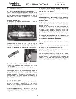
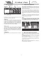
Transmitter cry-
stals are marked
with TX + chan-
nel number
Receiver cry-
stals are marked
with RX + chan-
nel number
Crystals for dual
conversion super-
hets are marked
with RX-DS +
channel number
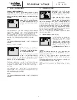
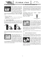
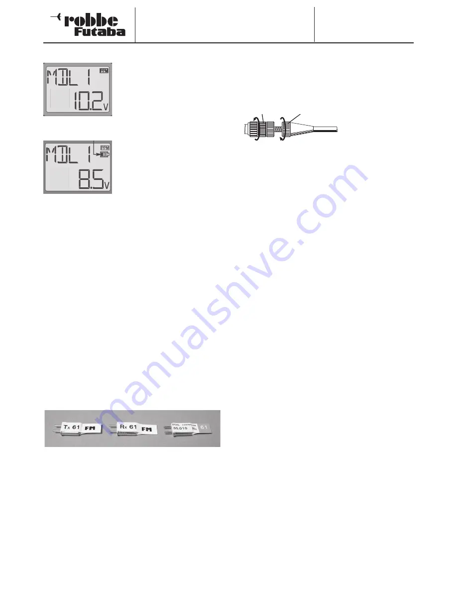
5.3 TRANSMITTER BATTERY VOLTAGE INDICATOR
The battery voltage status is shown
in the display. The voltage varies and
dependent on charge condition bet-
ween 10,8 V (full) and 9 V (nearly flat).
If the indicated voltage reaches 9.4 V,
then the battery needs recharging. If
the condition is such that 8.9V is dis-
played, you must stop operation and
recharge before continuing.
As soon as the voltage reaches 8.5
V, an acoustic and optical alarm will
go off to draw your attention that the
battery is flat and you must immedi-
ately turn off the transmitter and re-
charge.
5.4 OPERATION TIME
Using a 1500 mAh NiMH battery pack, the transmitter will have an
operating time of between 8 and 9 hours.
The receiver operation time, on the other hand, is dependent
upon the number of servos and friction in the control linkages as
well as the frequency that they are moving. One servo typically
draws between 150 and 600 mA in normal operation. Idle current
is 5-8 mA.
Once the servo reaches its commanded point (neutral, end or in
between position), the motor returns to an idle current, provided
that the linkages have no friction, and that the servo is not rea-
ching a mechanical limit. (A buzzing servo is drawing a heavy
current and can drain a battery very quickly!)
6.
CRYSTAL CHANGE
Your transmitter and receiver may be operated on varying fre-
quency channels within the 40 MHz band. Matching transmitter
and receiver crystals must be fitted to their respective sockets in
the transmitter and receiver cases. The channel number of both
transmitter and receiver crystal must be the same for the system
to work.
To change the transmitter crystal, you must open the transmitter
case back; see section 7.2.
It is not possible use 35 MHz crystals in a 40 MHz receiver;
the receiver will not work.
7.
TRANSMITTER ADJUSTMENTS
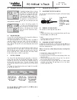
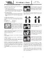
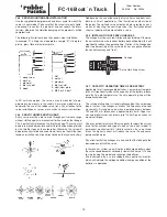
7.1 ADJUSTMENT OF STICK LENGTHS
The stick length may be adjusted in length to suit the best feeling
for the driver.
• Loosen Part A
and B
• Adjust stick length
to suit by screwing
in or out
• Lock part B against
part A
7.2 REMOVAL OF REAR COVER
The rear cover is held in place by two latches.
To Open
• Slide the two latches on case underside outwards and lift cover
• Remove/replace transmitter crystal
To close
• Carefully replace cover back into the case
• Close two latches to secure
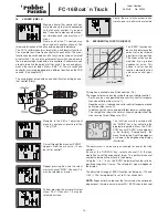
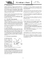
7.3 CHANGING OF THROTTLE RATCHET
As delivered, the throttle stick is on the left hand side (Mode 2), if
required, the throttle control may be moved to the right hand stick
unit by the following means:
Remove rear cover as described previously: (Looking from
rear of case)
1 Loosen return spring on right hand stick unit
2 Install spring on left hand stick
3 Locate the spring on the left hand neutralising gimbal using
long nose pliers
4 Remove neutralising arm from left hand stick, This stick has
now a ratchet friction on the vertical axis
5 Fit the neutralising arm to right hand stick unit. Locate spring
with pliers on the hook. The right hand stick unit has now a
self-centring vertical axis.
Part A
Part B


