Order Number
40 MHz No. F4044
FC-16 Boat `n Truck
8
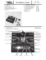
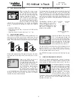
Position 3
Locate spring in left hand ver-
tical neutralising gimbal and
remove gimbal.
Position 5
Fit neutralising gimbal in right
hand stick. Hang spring on
the gimbal.
Position 1
loosen right hand throttle
spring
Position 2
Install spring on left stick
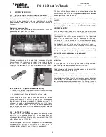
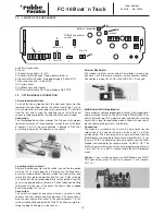
Receiver (Rx)
Switch
To battery
Take care to
ensure correct
polarity.
Charge
socket
(Channel 1)
Steering
(Channel 2)
(Channel 4)
Linear propor-
tional (chan. 5)
Linear propor-
tional chan. 6
Throttle
(Channel 3)
B
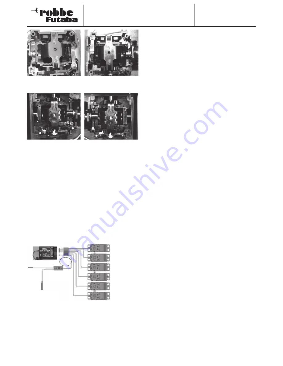
7.4 SERVO CONNECTION
The stick control functions for throttle, steering etc. are to be
found in channels 1-4. Channels 5 and 6 are linear proportional
channels with slider potentiometers.
Channels 7 and 8 may be used either with switches or opera-
ted with Multi-Modules.
The diagram illustrates the channel allocation on the Rx. Socket
“B” is used as an Rx battery connection or the battery may be
plugged into any of the other free channel outputs on the Rx.


