background image

9

Accessories


- Omega holder (2 pieces)................................99010420

Optional accessories:


- Objective°...................................................99000


- Lens-module 8°............................................990000


- Mounting plate................................................99009

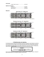
Beampath:


12. Maintenance and cleaning

It is absolutely essential that the fixture is kept clean and that dust, dirt and smoke-fluid residues must not build 

up on or within the fixture. Otherwise, the fixture‘s light-output will be significantly reduced. Regular cleaning will 

not only ensure the maximum light-output, but will also allow the fixture to function reliably throughout its life. 

A soft lint-free cloth moistened with any good glass cleaning fluid is recommended, under no circumstances 

should alcohol or solvents be used!

DANGER !

Disconnect from the mains before starting any

maintenance work

The front  objective lens will require weekly cleaning as smoke-fluid tends to building up residues, reducing the 

light-output very quickly. The cooling-fans should be cleaned monthly.

Summary of Contents for clubspot 250 CT

Page 1: ... Version 1 5 ...

Page 2: ...12 connection connection between fixtures 14 5 ClubSpot 300 DMX Protocol version 1 1 15 6 Controller operation 17 6 1 DMX addressing 17 6 2 Remotely controllable functions 17 7 Stand alone operation 18 8 Control menu map 19 9 Control menu 21 9 1 Fixture Address 21 9 2 Slave control 21 9 3 Fixture informations 21 9 4 Personality 22 9 5 Lamp On Off 23 9 6 Test sequences 23 9 7 Stand alone setting 24...

Page 3: ...r caution Make sure that the available voltage is not higher than stated on the rear panel Always plug in the power plug least Make sure that the power switch is set to OFF position before you connect the device to the mains The power plug has to be accessable after installing the device Make sure that the power cord is never crimped or damaged by sharp edges Check the device and the power cord fr...

Page 4: ...e correct holes only Only operate the fixture after having checked that the housing is firmly closed and all screws are tightly fas tened The lamp must never be ignited if the objective lens or any housing cover is open as discharge lamps may explose and emit a high ultraviolet radiation which may cause burns The maximum ambient temperature must never be exceeded Otherwise the lamp is switched off...

Page 5: ...pot 300 CT 1 Top cover of the head 2 Base 3 Yoke 4 Handle Rear panel 5 Power switch 6 Fuse holder 7 Power cord 8 3 pin DMX input 9 3 pin DMX output Front panel 10 Display 11 Mode button 12 Enter button 13 Up button 14 Down button ...

Page 6: ... follow the lamp manufacturer s no tes Do not touch the glass bulb with bare hands during the installation Make sure that the lamp is installed tightly into the lampholder system Adjust the optimal distance 1 1 5 mm from the lens by turning the screw A see the drawings Lamp adjust ment below on the rear panel of the head Then close the small lamp cover by tighten 3 fastening screws again Reclose t...

Page 7: ...its intensity by moving the lamp closer to the reflector Do so by turning the srew A until the light is evenly distributed If the light on the edge seems to be brighter as in the center the lamp is too close at the reflector In this case you need to move the lamp away from the reflector until the light is evenly distributed and the beam appears bright enough 4 3 Installation of an optional lens Th...

Page 8: ... gobos with the device switched off only Unplug from mains before It is possible to change 2 gobos on the static gobo wheel Open the top cover of the head by loosening the 4 fastening screws on the top cover Remove the fixation ring with an appropriate tool Remove the gobo and insert the new gobo Press the fixati on ring together and insert it in the front of the gobo standard 15 lens 18 lens 18 l...

Page 9: ... Earth 4 6 Changing the power supply settings magetic ballast Both the transformer and the ballast must be connected correctly for the local AC voltage and frequency The wrong settings can cause poor performance or demage of the moving head The factory settings are printed next to the power switch If you want to change the power supply settings follow the instructions 1 Disconnect the fixture from...

Page 10: ...10 US version ...

Page 11: ... where persons may walk by or be seated IMPORTANT OVERHEAD RIGGING REQUIRES EXTENSIVE EXPERIENCE including but not limited to calculating working load limits installation material being used and periodic safety inspection of all installation material and the projector If you lack these qualifications do not attempt the installation yourself but instead use a professional structural rigger Improper...

Page 12: ...ten the fixation screw Fixation via the omega holders 1 Bolt each clamp 1 to the omega holder 4 with M12 bolt and lock nut through the hole in the holder 2 Fasten the omega holders on the bottom of the base by inserting both quick lock fasteners 3 into the holes of the base and tighten fully clockwise 3 Fasten the safety rope 2 through the two apertures on the bottom of the base and over the truss...

Page 13: ...h the holes in the mounting plate 4 2 Insert the 4 quick lock fasteners 3 into the holes on the bottom of the base and tighten fully clockwise 3 Fasten the safety rope 2 through the two apertures on the bottom of the base and over the trussing sys tem 1 Clamp 2 Safety rope 3 Quick lock fasteners 4 Mounting plate ...

Page 14: ...e in the DMX chain with the DMX input of the next fixture Always connect one output with the input of the next fixture until all fixtures are connected Caution At the last fixture the DMX cable has to be terminated with a terminator Solder a 120 Ω resistor between Signal and Signal into a 3 pin XLR plug and plug it in the DMX output of the last fixture Building a master slave chain Connect the DMX...

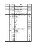
Page 15: ...nction Lamp Off after 3 sec No function proportional step step step step 7 7 5 0 10 21 32 42 53 64 74 85 96 106 117 128 189 190 193 194 255 Colours Continual positioning Open White Turquoise Deep red Cyan UV filter Magenta Light blue Yellow Green Pink Blue Red Forwards rainbow effect from fast to slow No rotation Backwards rainbow effect from slow to fast proportional proportional proportional pro...

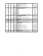
Page 16: ...o indexing Forwards gobo rotation from fast to slow No rotation Backwards gobo rotation from slow to fast proportional proportional step proportional 13 13 11 No function 14 14 12 0 255 Focus Continuous adjustment from far to near proportional 15 15 13 0 31 32 63 64 95 96 127 128 143 144 159 160 191 192 223 224 255 Shutter Strobe Shutter closed Shutter open Strobe effect from slow to fast Shutter ...

Page 17: ...ons Lamp A relay inside of the ClubSpot 300 allows you to switch on and off the lamp via the control panel or via your DMX controller without affecting the rest of the lighting To switch On Off the lamp please refer to Lamp On Off menu LAMP Note It is also important to note that the discharge lamp is cold restrike types that means that they have to be cold before re striking For this reason you ha...

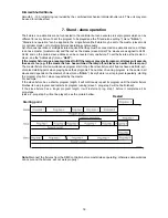
Page 18: ...a reset switches On Off the lamp or plays test program all slaves will execute these acts too e g if the master fixture has switched the lamp off no slaves can switch the lamp on The master fixture starts simultaneous program start in the other slave fixtures All fixtures have a definite syn chronized starting point when playing back their programs The number of running program is the same in all ...

Page 19: ...tl rSEt La ti totl rSEt LA St totl rSEt Hi tE totl rSEt tEMP DM In Pan 0 255 dim 0 255 VErS PErS r PAn On Off r tilt On Off 16br Mod1 Mod2 8bit LA Pr LA Au On Off d L OF On Off dM On On Off dM OF On Off En Sn On Off dISP turn On Off d On On Off d Int 20 100 bL Co On Off FEEd On Off FAn S Auto HIGH rEG LoOF LoHI dF SE ...

Page 20: ... PrG 1 PrG 2 PrG 3 PLAY tESt PrG 1 PrG 2 PrG 3 Edit PrG 1 PrG 2 PrG 3 St 01 St 99 Pan 0 255 S tim 0 1 25 5 s COPY rESE SPEC MAnu Pan Pan1 Pan2 Pan3 dimr dim0 dim4 dimC LA Ad PAn 0 255 tilt 0 255 Foc 0 255 CodE AdJ Pan 0 255 F CAL Colo 0 255 EFFE 0 255 r Gob 0 255 G rot 0 255 A rES ...

Page 21: ...e as a Master or Slave Slave1 Slave 9 Option d AbL deactivates master slave setting 9 2 Slave control This function allows you to control the slaves from the master s control panel in a master slave operation Select this function from the main menu and press ENTER Browse the list of all connected slaves SL C 1 SL C 9 by pressing UP or DOWN Select the desired slave and press ENTER button The matchi...

Page 22: ...hat the outside temperature should not exceed 45 C DM In Readout of DMX values Select this function to read DMX values 0 255 of each channel received by the fixture PAn a coarse pan movement EFFE a prism F PAn a fine pan movement Prot a prism rotation tilt a coarse tilt movement r Gob a rotating gobo wheel F tilt a fine tilt movement G rot a gobo rotation SpEd a pan tilt speed Foc a dimmer Func a ...

Page 23: ...and the feedback is switched on again the moving head might not to be synchronized with the DMX signal You have to make a reset in order to synchronize the moving head with the DMX signal Fan S Fan speed operating modes By using this function you can choose 3 types of the fans speed op erating modes Auto The fan automatically raises its speed in order to control inside temperature of the head HIGH...

Page 24: ... step time Step time the time during which effects last in the current step If the fixture is set as a master then you may edit any program in the slaves You can t edit programs on the slave fixtures from their control panels if the master fixture is switched on and connected to the slaves editing is possible by the master control panel only Procedure 1 Press UP or DOWN to select the program you w...

Page 25: ...right value from 0 to 255 Then press ENTER to confirm or MODE to cancel and return to the menu This can be repeated for each calibration parameter if it is required When the calibration is finished it is necessary to use the A rES function in order to write the calibration values to the memory EPROM and to make a reset in order to check the newly adjusted positions of the colour and gobo wheels Wh...

Page 26: ... its driver circuit on the main PCB The rotating gobo wheel is not located in the default position after the reset iGEr rotating gobo indexing error This message will appear after the reset of the fixture if the magnetic indexing circuit malfunctions sensor failed or magnet missing or the stepping motor is defective or its driver circuit on the main PCB The rotating gobo is not located in the defa...

Page 27: ...le Gobo dimensions outside diameter 26 8mm thickness 1 1mm high temperature borofloat or better glass image diameter 22 mm Effect glass gobo outside diameter 26 8 mm max thickness 4mm high temperature borofloat or better glass 3 black and white gobos and 2 effect glass gobos are included Strobe Strobe effect with variable speed max 10 flashes per second Preprogrammed variable random strobe and dim...

Page 28: ...ontrollable speed of pan tilt movement for easy programming Movement control tracking and vector Rigging Stands directly on the floor Mounts horizontally or vertically with 2 Omega brackets 2 truss orientation Safety chain cord attachment point Temperatures Maximum ambient temperature 45 C Maximum housing temperature 80 C Minimum distances Min distance from flammable surfaces 0 5m Min distance to ...

Page 29: ...will be significantly reduced Regular cleaning will not only ensure the maximum light output but will also allow the fixture to function reliably throughout its life A soft lint free cloth moistened with any good glass cleaning fluid is recommended under no circumstances should alcohol or solvents be used DANGER Disconnect from the mains before starting any maintenance work The front objective len...

Page 30: ...amp Maintenance and service operations are only to be carried out by authorized dealers Replacing the fuse If the lamp burns out the fine wire fuse of the device might fuse too Only replace the fuse by a fuse of same type and rating Before replacing the fuse unplug mains lead Procedure 1 Unscrew the fuseholder on the rear panel of the base with a fitting screwdriver from the housing anti clockwise...

Page 31: ...31 ...

Reviews: