background image

26

Commissioning

5.6

Installing the suction hose bracket for cleaning

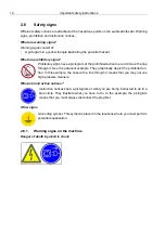
Attach the suction hose bracket for cleaning the automatic feeder in the vicinity of the feed-
ing station.

NOTICE!

The suction hose bracket must be installed higher than the position of the mixer so that
the cleaning water cannot flow out of the hoses.

5.7

Installing the safety grid for the powder hopper attachment

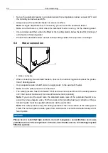
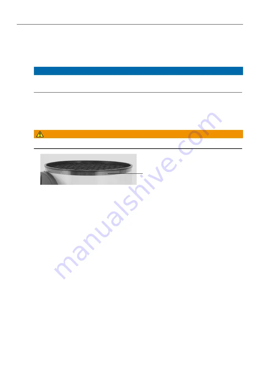
The protective grid for the powder hopper attachment prevents you from being injured by the
rotating tools in the powder hopper, for example when pouring in milk powder.

WARNING!

To avoid injuries, the protective grid must always be mounted during operation

1 Opening on the powder hopper attachment for screwing in a self-tapping screw

Proceed as follows for the installation of the protective grid:

1. Turn off the automatic feeder using the main switch and disconnect the power plug.

2. Remove the bag with the small parts and hoses as well as the operating manual from the

powder hopper.

3. Insert the safety grid for the powder hopper attachment.

4. Screw the three self-tapping screws into the holes provided for this purpose.

5. Fill the powder container with milk powder (see 6.1 "Filling the powder container" ).

5.8

Filling the boiler

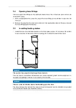
Plug in the power plug and turn the main switch clockwise to 

ON

.

Note:

 After the control unit has been switched on, the program version and the portion count

appear briefly in the display before the automatic feeder carries out a test routine. Do not
press any buttons on the control panel during these initial routines.

Note:

 After the initial routine has concluded, water runs into the mixer automatically for up

to 180 seconds. As soon as the mixer electrode is covered, the boiler is filled and the auto-
matic feeder switches into automatic operation. 

1

Summary of Contents for TAP5-EZ2-32-F4

Page 1: ...Original Operating Manual ECO automatic lamb feeder Program version 01 01 and higher TAP5 EZ2 32 F4 TAP5 EZ2 50 F4 May 23 2018 ...

Page 2: ...wner 10 2 2 2 Necessary qualifications of the service technician 10 2 3 Residual risks 10 2 4 Your duties 11 2 5 How am I warned of hazards 12 2 5 1 What are the components of a hazard description 13 2 5 2 Potentially fatal hazards or health hazards 13 2 5 3 Material damage 13 2 6 Safety signs 14 2 6 1 Warning signs on the machine 14 2 6 2 Signs on the machine 15 2 7 Safety devices 16 3 Hygiene 19...

Page 3: ...tting the milk powder 28 6 Operation 29 6 1 Filling the powder container 29 6 2 Feed preparation 29 6 3 Feed distribution 29 6 4 Portion sizes 29 6 4 1 Setting the water 30 6 4 2 Setting the milk powder 30 7 Cleaning 31 7 1 Cleaning agents 32 7 2 Preparing for cleaning 32 7 2 1 Water and detergent amounts in the main cleaning cycle 32 7 3 Cleaning the mixer jar 32 7 4 Cleaning the suction hose 34 ...

Page 4: ...g of cables 42 10 4 Disposing of the circuit board 42 10 5 Disposal of the automatic feeder 42 11 Care and maintenance schedule routine tasks 43 11 1 Safety instructions 43 11 2 Maintenance intervals and activities 44 11 3 Checking components for compliance with national regulations 45 12 Appendix 46 12 1 Checklist for commissioning and recommissioning 46 12 2 Materials list 47 12 3 Shutdown check...

Page 5: ...ead and understood the safety chapter see 2 Important safety instructions Resolve any questions with your service technician before commissioning the feeder Keep this operating manual and the safety data sheets for the cleaning agent readily avail able at all times and pass them on to the next user Observe all of the warnings and safety instructions in this operating manual at all times 1 1 Transp...

Page 6: ...andle 5 Control unit 6 On the right in the machine housing Water valve electronic boiler overheating protection 7 Water connection 8 Height adjustable feet 9 Mixer mixer jar mixer motor 10 Hose connections 11 Mixer heating system optional 12 Rod electrode 13 Milk powder discharge 14 Water outlet 15 Name plate not shown 1 2 3 5 6 7 9 10 11 13 14 15 4 12 8 ...

Page 7: ...r 1 3 Technical data 1 3 1 Electrical connection Note The data for the electrical connection can be found on the name plate on the left side of the base frame 1 3 2 Dimensions 1 3 3 Weight approx 34 kg 1 870 565 650 343 515 1135 ...

Page 8: ...ttachment approx 35 kg 1 3 7 Number of feeding stations and animals TAP5 EZ2 50 F4 up to 8 feeding stations with 25 30 lambs each TAP5 EZ2 32 F4 up to 6 feeding stations with 25 30 lambs each 1 3 8 Name plate The name plate is located above the left side door on the outside of the automatic feeder It con tains information about the manufacturer type and number of the automatic feeder information a...

Page 9: ...ber and model are located on the name plate on the left of the automatic feeder housing When commissioning your automatic feeder ask your service technician for the device number series type and program version You can note the device type serial number and program version in the fields provided Device type Serial number Program version Our contact details Förster Technik GmbH Gerwigstrasse 25 782...

Page 10: ... the relevant standards They have knowledge of relevant accident pre vention regulations generally accepted safety regulations and country specific standards and provisions 2 3 Residual risks Hazards to health caused by the automatic feeder WARNING Danger from electric current The automatic feeder is powered by electricity You must observe the general precautions for handling electrical equipment ...

Page 11: ...eration Carry out the recommended maintenance on the hoses The mixer and powder supply may start up unexpectedly Never reach into the area of the mixer or powder supply while the automatic feeder is in operation Only use the scraper sup plied to clean the powder discharge opening Chemical burn The cleaning agent used to clean the automatic feeder contains caustic substances They can cause severe i...

Page 12: ...t safety devices Visually inspect the automatic feeder for possible damage You can find a care and mainte nance schedule in the appendix see 11 2 Maintenance intervals and activities which provides recommendations on how often you should check different parts of the automatic feeder Repair any damage to the automatic feeder or if you are not authorized to or capable of do ing this yourself have it...

Page 13: ...warning triangle with exclamation mark and the following hazard words DANGER The word DANGER indicates an imminent hazard that will lead to death or serious injury Warning signs in the operating manual DANGER white text on red background WARNING The word WARNING indicates a potentially hazardous situation that could lead to death or serious injury Warning signs in the operating manual WARNING blac...

Page 14: ...a line through it See the adjacent example They graphically depict the prohibited ac tion In this example the hose with a line through it means that you may not use high pressure cleaners What are instruction notices Instruction notices show a pictogram of what you are being instructed to do in a blue circle They illustrate what you have to do In the example the pictogram means that you must alway...

Page 15: ...ning scalding Danger due to dry run of the heating system Automatic startup No spraying Grounding symbol 2 6 2 Signs on the machine The meanings of the individual signs attached to the outside or inside of the machine are de scribed below ...

Page 16: ...er in the event of overheat ing temperature rises above 70 C The heater may only be reactivated by a service engi neer Safety grid for the powder hopper attachment The safety grid prevents people from being injured by the rotating tools in the hopper for example when adding milk powder It must al ways be installed when the unit is operating The scraper next to milk powder discharge The powder disc...

Page 17: ...er illustrated below 1 Cover of the safety temperature limiter NOTICE The heating system must be checked by a service technician if the safety temperature limiter is triggered more than once Protective grid for powder hopper attachment The protective grid for the powder hopper attachment prevents you from being injured by the rotating tools in the powder hopper for example when pouring in milk pow...

Page 18: ... into the hazardous area of the powder discharge opening The powder dosing can start up automatically at any time crushing or cutting off your fingers Always turn off the automatic feeder using the main switch and disconnect the power plug Only use the scraper supplied to clean the powder discharge opening ...

Page 19: ...ion increases with the number of germs When germs get into your animal feed such as milk they can spoil the feed and make it ined ible When germs attack your lambs for example from infected feed or other infected lambs your lambs can become sick and die Both situations result in costs that you can minimize by taking measures to ensure hygienic con ditions As a farmer it is your job to identify sou...

Page 20: ...or instructions and not their des ignations Keypad symbol Function Automatic mode Temperature control of boil er portion counter Reset portion counter Start stop mixer Manual function water Manual function MP Heat up cleaning water MP quantity setting Water quantity setting Boiler temperature setting ...

Page 21: ...ey to query the boiler temperature Press this key again to query the number of positions Press this key to set the portion counter to 0 Press this key to start stop the mixer maximum running time 3 minutes Press these keys to dispense water or MP directly into the mixer Press this key to heat the cleaning water up to the cleaning temperature 55 C once Press these keys to set the dosing quantity of...

Page 22: ... to return to automatic mode press Note The automatic feeder is in automatic mode if the diode on the left next to Auto is lit If you press for example to set the dosing quantity of the MP the automatic mode is inter rupted 4 3 2 Offline mode If the automatic feeder is in offline mode the feeding is interrupted If you want to return to au tomatic mode you must press The lit diode next to the Auto ...

Page 23: ...vided by the customer lightning protection measure Comply with the local regulations and safety measures Potential equalization To protect the animals and prevent electrical faults subject all metallic objects such as water pipes feeding station and automatic feeder to potential equalization The connecting screw to ground the automatic feeder is on the right hand side of the machine housing direct...

Page 24: ... water Use a separate water shutoff valve to supply water to the automatic feeder Make sure the water pressure is consistent The water pressure must be at least 2 5 bar and must not exceed 6 bar If the water pressure of 2 5 bar cannot be insured then retool the water tank optional Note If you retool the water tank the standard water valve of the automatic feeder is re placed by a low pressure valv...

Page 25: ...tall the teat at its intended location on the front plate approx 10 cm above the suction hose connection of the mixer and the resulting 40 cm above the lamb s floor level NOTICE The suction hose must not be longer than 2 meters This can lead to malnutrition Malnutrition can cause impaired growth and development in creased susceptibility to illness or even death of the animals NOTICE There is a ris...

Page 26: ...id 1 Turn off the automatic feeder using the main switch and disconnect the power plug 2 Remove the bag with the small parts and hoses as well as the operating manual from the powder hopper 3 Insert the safety grid for the powder hopper attachment 4 Screw the three self tapping screws into the holes provided for this purpose 5 Fill the powder container with milk powder see 6 1 Filling the powder c...

Page 27: ...the cleaning agent and wear the specified safety equipment 5 11 Setting the target temperature During commissioning the target temperature of the water in the boiler must be set The mini mum temperature is always 3 C below the target temperature and cannot be set 1 Exit automatic mode by pressing 2 Press the LED next to the key lights up and a set temperature appears in the control unit display 3 ...

Page 28: ...tlet and press In the time that is indicated in the control unit display a certain amount of water is dispensed 4 Measure the collected quantity 5 Using or change the time as needed so that the desired amount is dispensed into the measuring vessel 6 Press again and measure the dispensed amount 7 Repeat the procedure until the desired amount has been precisely dispensed 5 12 2 Setting the milk powd...

Page 29: ...ment increased susceptibility to illness or even the death of your animals 6 2 Feed preparation During feed preparation water is dispensed first which is conducted to the mixer jar via the boil er causing it to heat up If the mixer jar is filled up to the rod electrode with water milk substitute MP will be dispensed from the powder container into the mixer jar When the lab sucks the feed the mixed...

Page 30: ...d measure the dispensed amount 7 Repeat the procedure until the desired amount has been precisely dispensed 6 4 2 Setting the milk powder 1 Press to exit automatic mode 2 Press The LED next to the key lights up 3 Hold an empty measuring vessel under the powder outlet and press In the time that is indicated in the control unit display a certain amount of MP is dispensed 4 Measure the collected amou...

Page 31: ... the cleaning intervals recommended by the manufacturer of the cleaning agent as well as those recommended in this operating manual see 11 2 Maintenance intervals and activities Only use the cleaning agents recommended in this operating manual Observe the manufacturer s guidelines regarding the amount temperature and concentra tion of cleaning agent used Do all of the cleaning recommended in this ...

Page 32: ...he cleaning agent manufacturer s dosage recommendations We recom mend scheduling the cleaning in a time when there is not much feed entitlement 2 If you are manually putting in the cleaning agent have the respective cleaning agent amount ready in order the reach the desired concentration in the main cleaning cycle 7 2 1 Water and detergent amounts in the main cleaning cycle Water amount approx 1 3...

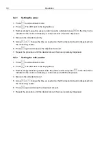
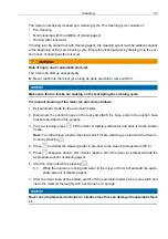
Page 33: ...er 2 Disconnect the suction hoses on the teat and attach the hose ends in the suction hose brackets provided for this purpose 3 For pre cleaning press Fill the mixer completely with water and drain it via the suction hoses Note You will achieve a better cleaning result if for pre cleaning you also start the mixer in terval by pressing 4 Press and allow the cleaning water to pre heat to the cleanin...

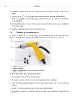
Page 34: ...he suction hose a cleaning sponge is pressed through the suction hose with water pressure using the hose cleaning pistol Perform the hose suction cleaning as needed 1 Water hose connection 2 Cleaning sponge 3 Cleaning sponge injector with suction hose connection 4 Quick coupling To clean the suction hose proceed as follows 1 Exit automatic mode for the automatic feeder 2 Remove the suction hose fr...

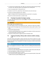
Page 35: ...ve there 1 Switch off the automatic feeder 2 Clean the powder discharge with the tool supplied in the delivery Catch the loosened de posits and milk powder and dispose of them 3 Switch the automatic feeder on again and put it into automatic mode 7 6 Thorough cleaning of the powder container with the dosing unit A thorough cleaning of the powder container with dosing unit is done as needed but no l...

Page 36: ...rid for the powder hopper attachment and tighten the three screws in the holes provided for this purpose 8 Only fill with milk powder when the feeder is to be used again 9 Switch the automatic feeder on again and set the milk powder dosage see 6 4 2 Setting the milk powder ...

Page 37: ...rted in an upright position To ensure that the automatic feeder does not become a breeding ground for germs which could endanger the health and life of your animals when you restart the feeder you must thoroughly clean the automatic feeder before shutting it down Clean the mixer the suction hoses and the powder container After cleaning you must disconnect the power and water supply and empty the b...

Page 38: ...from the water tap that supplies the automatic feeder with water and from the water connector on the automatic feeder 4 Dispose of the water hose New hoses are available from your dealer NOTICE Beware of the risk of infection To prevent infections use a new hose when recommissioning the unit 5 Disconnect the hose that leads from the teat to the mixer jar 6 Dispose of the hose New hoses are availab...

Page 39: ... of the materials used to make the automatic feeder see 12 2 Materials list 1 Perform steps 2 to 13 of the shutdown see 8 1 Temporary shutdown You do not have to perform step 1 cleaning 2 Dispose of any residual cleaning agent See the data sheet of the cleaning agent for infor mation on the disposal of the cleaning agent WARNING Chemical burns due to the cleaning agents used The cleaning agent can...

Page 40: ...If the mixer electrode is covered with water a decimal point will appear in the control unit display next to the boiler temperature 9 1 2 Overheating E 2 If overheating occurs the message E 2 appears in the display Press and remove water from the boiler until the target temperature is reached 9 1 3 Safety temperature limiter of the boiler E 3 If there is a short circuit or a breakage of the safety...

Page 41: ...omatic feeder 3 Remove the metal cover under which the safety temperature limiter is located 4 Press the red reset button in order to reset the safety temperature limiter 5 Attach the metal cover and close the side door 6 Reinsert the power plug and turn the main switch back to the ON position 9 1 5 Boiler not filled E 5 If the boiler is not filled the message E 5 appears in the display Press and ...

Page 42: ...r eyes or hands Always wear safety glasses and protective gloves when using cleaning agents Follow all the safety instructions listed in the safety data sheet for the cleaning agent and wear the specified safety equipment 10 2 Disposing of hoses Dispose of hoses as controlled waste or municipal waste depending on the material Read the disposal instructions on the packaging of the hoses or contact ...

Page 43: ...ian 11 1 Safety instructions DANGER Fatal electric shock The electrical components of the automatic feeder are live Always turn off the automatic feeder with the main switch first and disconnect the power plug before carrying out any work on the automatic feeder WARNING Risk of burns due to hot surfaces The solenoid valves can reach temperature of up to 100 C during operation or malfunctions This ...

Page 44: ...en using cleaning agents Follow all the safety instructions listed in the safety data sheet for the cleaning agent and wear the specified safety equipment NOTICE An interruption in feeding operation means that your animals will not receive any feed This can lead to malnutrition Malnutrition can cause impaired growth and development in creased susceptibility to illness or even the death of your ani...

Page 45: ...nctioning of electrodes and mixer blades Visually inspect mixer for leaks Visually inspect the effectiveness of the cleaning cycles Suction hose and teat Visually check the suction hose and teat for damage and wear and clean them if necessary see 7 4 Cleaning the suction hose Replace all milk hoses from the mixer to the feeding station Powder conveyor Check powder discharge opening for foreign bod...

Page 46: ...lity Excessive calcium and or iron and or manganese concentrations may cause premature wear Tell end users that the feeder and cables must be protected against exposure to sun light Set up the automatic feeder on an even surface Electrically ground the automatic feeder Connect water supply Install the feeding station Install suction hoses Install the suction hose bracket for cleaning Install safet...

Page 47: ...ater hose between the water solenoid valve and the boiler and open the vent screw on the cover of the boiler to allow the water to flow out Once the boiler has been completely drained reattach the water hose and tighten the vent screw Disconnect and dispose of the water hose and suction hoses Empty the milk powder container Basic cleaning of the powder container and dosing unit Clean the outside o...

Page 48: ...on sizes 28 Setting the target temperature 27 Setting the water 28 30 Setting up the automatic feeder 23 Water connection 24 Water pressure 24 Components 6 6 Correction keys 21 D Delete 21 Device number 9 Dimensions 7 Disposal Automatic feeder 42 Cable 42 Circuit board 42 Cleaning agents 42 Hoses 42 E Electrical connection 7 23 Electrical connection provided by the customer 23 F Faults E 1 40 E 2 ...

Page 49: ...on Owner 10 R Recommendations for the temperature settings 27 Removal from service 37 Residual current circuit breaker 23 Residual risks 10 Routine tasks 43 S Safety devices 16 Safety notices 14 Safety signs Warning signs 14 Safety temperature limiter 17 40 Scraper next to milk powder outlet 17 Service technician 10 Setting keys 21 Setting the milk powder 28 30 Signs 15 Start key 21 Start stop mix...

Page 50: ...tive 95 16 EG recast 2014 30 EU Directive 2014 30 EU of the European Parliament and of the Council of 26 February 2014 on the harmonisation of the laws of the Member States relating to electromagnetic compatibility recast Reference to the harmonised standards used as referred to in Article 7 2 EN ISO 12100 2010 11 Safety of machinery Electrical equipment of machines Part 1 General requirements ISO...

Reviews: