background image

20

© 2020 Robern, Inc. 701 N. Wilson Ave. Bristol, PA  19007  U.S.A.
800.877.2376      

www.robern.com


Instructions d'installation  / Instrucciones de instalación 

No. de pièce / Pieza n.

°

 209-1289   rev. 03/10/20

Profiles Framed Cabinet  /  Profiles Framed Gabinete

PC1230D4 PC1630D4 PC2030D4 PC2430D4 PC1240D4 PC1640D4 PC2040D4 PC2440D4 PC1648D4 PC2048D4 PC2448D4 PC1230D6 PC1630D6 PC2030D6 PC2430D6 PC1240D6 PC1640D6 PC2040D6 PC2440D6

A

11-1/4"  

(286 mm)

15-1/4"  

(387 mm)

19-1/4"  

(489 mm)

23-1/4"  

(591 mm)

11-1/4"  

(286 mm)

15-1/4"  

(387 mm)

19-1/4"  

(489 mm)

23-1/4"  

(591 mm)

15-1/4"  

(387 mm)

19-1/4"  

(489 mm)

23-1/4"  

(591 mm)

11-1/4"  

(286 mm)

15-1/4"  

(387 mm)

19-1/4"  

(489 mm)

23-1/4"  

(591 mm)

11-1/4"  

(286 mm)

15-1/4"  

(387 mm)

19-1/4"  

(489 mm)

23-1/4"  

(591 mm)

B

30" (762 mm)

39-3/8" (1000 mm)

48" (1219 mm)

30" (762 mm)

39-3/8" (1000 mm)

RO (A)

10-1/2"  

(267 mm)

14-1/2"  

(368 mm)

18-1/2"  

(470 mm)

22-1/2"  

(572 mm)

10-1/2"  

(267 mm)

14-1/2"  

(368 mm)

18-1/2"  

(470 mm)

22-1/2"  

(572 mm)

14-1/2"  

(368 mm)

18-1/2"  

(470 mm)

22-1/2"  

(572 mm)

10-1/2"  

(267 mm)

14-1/2"  

(368 mm)

18-1/2"  

(470 mm)

22-1/2" 

 (572 mm)

10-1/2"  

(267 mm)

14-1/2"  

(368 mm)

18-1/2"  

(470 mm)

22-1/2"  

(572 mm)

RO (B)

29-1/4" (743 mm)

38-5/8" (981 mm)

47-1/4" (1200 mm)

29-1/4" (743 mm)

38-5/8" (981 mm)

4-11/16" (119 mm)

6-5/8" (168 mm)

E

4" (102 mm)

6" (152 mm)

F

4-5/16" (110 mm)

9-3/4" (248 mm)

4-5/16" (110 mm)

9-3/4" (248 mm)

4-5/16"  

(110 mm)

9-3/4" (248 mm)

4-5/16" (110 mm)

9-3/4" (248 mm)

4-5/16" (110 mm)

9-3/4" (248 mm)

G

6-5/8" (168 mm)

5-3/4" (146 mm)

6-5/8" (168 mm)

5-3/4" (146 mm)

6-5/8"  

(168 mm)

5-3/4" (146 mm)

6-5/8" (168 mm)

5-3/4" (146 mm)

6-5/8" (168 mm)

5-3/4" (146 mm)

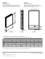
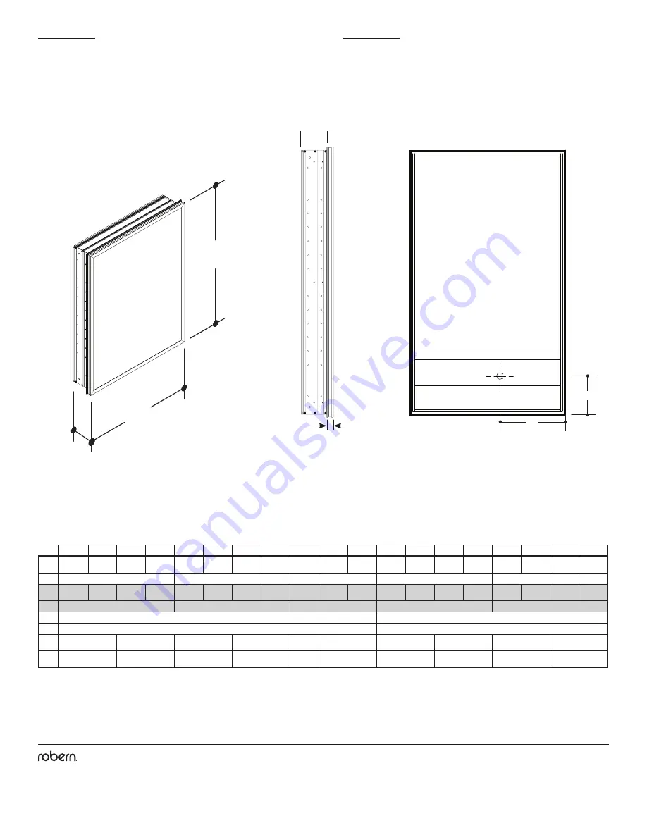
DIMENSIONS

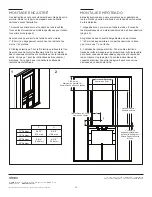
Déterminez les dimensions globales de l’armoire. Pour une 

armoire encastrée, déterminer les dimensions brutes. Voir le 

tableau pour les dimensions spécifiques selon le modèle.

A

B

D

Vista Isométrica

Vue isométrique

Vista trasera

Vue arrière

Vista lateral

Vue de côté

15/16

"


(24 mm)

E

Ouverture Brute (RO) pour installation encastrée dans le tableau ci-dessous / 

Apertura Áspera (RO) para instalación empotrada en la siguiente tabla Profundidad Del Empotrado

D4 = 4” minimum requis ou construction de 2X4 / D4 = 4” (102 mm) como mínimo requeridas o construcción 2X4

D6 = 6” minimum requis ou construction de 2X6 / D6 = 6” (152 mm) como mínimo requeridas o construcción 2X6

DIMENSIONES

Determinar gabinete y las dimensiones de. Si empotrar

gabinete, determinar las dimensiones toscamente en. Vea la 

tabla para las dimensiones específicas del modelo.

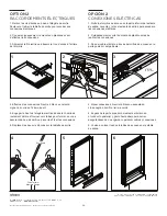
Câble Trou D’Accès /  

Cable Orificio de Entrada

F

G

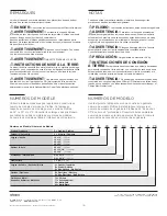
Summary of Contents for PC1230D4T Series

Page 1: ...he specific instruction for how your cabinet will be mounted The cabinets can be surface mounted or recess mounted Save these instructions for future use and reference An improper installation voids t...

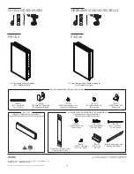
Page 2: ...ON ELEC 2430D4 NON ELEC 2030D6 NON ELEC 2430D6 NON ELEC 30 MSMK30D4P 40 MSMK40D4P 48 MSMK48D4P Optional for surface mounting 2 Z Mounting Bars 2 Glass Side Panel 203 1349 6 Wall Anchors SS712 3 Top Cl...

Page 3: ...wiring system or an equipment grounding conductor must be run with the circuit conductors and connected to the equipment grounding terminal or lead on the product WARNING An Electrical option cabinet...

Page 4: ...1 2 368 mm 18 1 2 470 mm 22 1 2 572 mm 14 1 2 368 mm 18 1 2 470 mm 22 1 2 572 mm 10 1 2 267 mm 14 1 2 368 mm 18 1 2 470 mm 22 1 2 572 mm 10 1 2 267 mm 14 1 2 368 mm 18 1 2 470 mm 22 1 2 572 mm RO B 2...

Page 5: ...to the equipment grounding terminal or lead on the product WARNING An Electrical option cabinet must be wired to a 20 Amp GFI Ground Fault Interrupter protected circuit when used in bathrooms and all...

Page 6: ...abinet Removing a small cover on the back of the cabinet allows FIELD POWER wires to be fully connected through an access on the rear of the cabinet The cabinet is fully wired before mounting in on th...

Page 7: ...the access screws from the plate located on the back of the cabinet Remove rear plate to access wires 2 Carefully cut plastic tie before making the connections 3 Feed the electric wire through the ac...

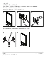
Page 8: ...ons 2 Carefully cut plastic tie before making the connections 3 Feed the electric wire through the access hole in the back of the cabinet OPTION 2 ELECTRIC CONNECTIONS 3 1 4 2 5 6 White Black Ground F...

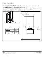
Page 9: ...e 5 Make sure cabinet door is at least 1 25 mm clearance to the top of the faucet and at least 1 from the ceiling 2 Electrical field wiring Pull electric wire through the hole Be sure to provide enoug...

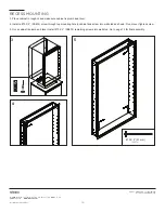
Page 10: ...inet RECESS MOUNTING 3 Place cabinet in rough in and make sure cabinet is plumb and level 4 Install a 10 X 2 SS674 screw through top mounting hole in cabinet and screw into wall stud as shown Do not o...

Page 11: ...installation 1 It is strongly recommended that the wall be framed behind the drywall or tile 2 Electrical field wiring Electrical feed through location is indicated below See page 5 for location See p...

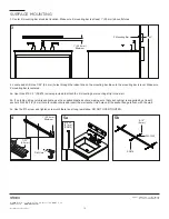
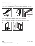
Page 12: ...ere 4 Locate and drill three 7 32 5 5 mm holes through the indent line on the mounting bar Be sure the mounting bar is level Make sure Z mounting bar is centered 5a Use three 10 X 2 SS674 screws provi...

Page 13: ...screws provided attach the top of the cabinet to the wall through the top clips as shown If no stud is available use wall anchors as described in step 5b SURFACE MOUNTING 7 8 SS672 8 SS676 9 10 3x 6...

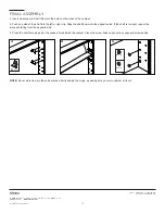
Page 14: ...SS666 over the elbow of the hinges to stop door swing radius at 110 1B 1A 1A 2A 2B 2A B The cabinet doors have a three way adjustment feature Height side to side level and depth can all be adjusted u...

Page 15: ...one side of the shelf into the left or right clip Snap the shelf down into the opposite side If the shelf is too tight repeat the process starting from the opposite side 5 Press the shelf hole plugs i...

Page 16: ...n one 1 year from the date of delivery ROBERN is not responsible for installation costs The warranty is void in the event the product is damaged in transit or if damage or failure is caused by abuse m...

Page 17: ...uvent tre retourn s Si vous rencontrez des probl mes avec votre cabinet contactez votre revendeur ou directement Robern AVERTISSEMENT porte outil accessoire magn tique peuvent tre nocifs pour les port...

Page 18: ...ON ELEC 1630D6 NON ELEC 30 MSMK30D4P 40 MSMK40D4P 48 MSMK48D4P Optionnel pour un montage en surface Opcional para montaje en superficie 2 Barre de Montage en Z Barra de Montaje en Z 2 Panneau Lat ral...

Page 19: ...te Nunca deje caer ni inserte ning n objeto en ninguna abertura No utilizar al aire libre ADVERTENCIA Riesgo de descarga el ctrica Conecte este mobiliario solo a un circuito debidamente conectado a ti...

Page 20: ...1 mm 47 1 4 1200 mm 29 1 4 743 mm 38 5 8 981 mm D 4 11 16 119 mm 6 5 8 168 mm E 4 102 mm 6 152 mm F 4 5 16 110 mm 9 3 4 248 mm 4 5 16 110 mm 9 3 4 248 mm 4 5 16 110 mm 9 3 4 248 mm 4 5 16 110 mm 9 3 4...

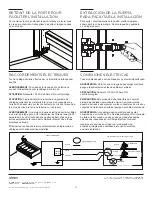
Page 21: ...nts requis par le National Electric Code Code lectrique national Effectuer les connexions in situ conform ment au diagramme de c blage pour l option lectrique install e RACCORDEMENTS LECTRIQUES CIRCUI...

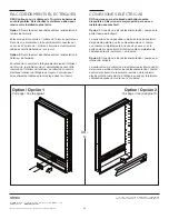
Page 22: ...ieur de l armoire Le retrait du couvercle lectrique int rieur de l tag re est requis L armoire peut tre enti rement c bl e apr s montage dans sur le mur OU O Option Opci n 1 Voir page Vea la p gina 9...

Page 23: ...cc s dans la plaque comme illustr 3 1 4 2 5 Blanc Blanco Noir Negro Sol Suelo Fil de terrain Alambre Campo 4 MAX 102 mm MAX OPCI N 1 CONEXIONES EL CTRICAS 1 Retire los tornillos de acceso de la placa...

Page 24: ...evante y retire el estante de salida para acceder a las conexiones el ctricas 2 Cuidadosamente corte la corbata de pl stico antes de realizar las conexiones 3 Pase el cable el ctrico a trav s del orif...

Page 25: ...lectrique MONTAGE ENCASTR 1 2 C bles Dans le Champ Cabledo de Campo 1 25 4 mm Espacement Minimum de la Porte Au Robinet M nimo Desde la Puerta al Grifo Ouverture Brute Abertura en Bruto Ouverture Brut...

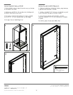
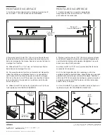
Page 26: ...u illustr Ne pas serrer trop les vis 5 Une fois que l armoire est d aplombs et niveau installez les vis 10 X 2 51 mm restantes dans les colombages Voir la page 16 pour l assemblage final 3 4 5 10 X 2...

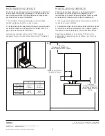
Page 27: ...binet et au moins 1 du plafond MONTAGE EN SURFACE 2 1 C bles Dans le Champ Cableado de Campo 1 25 4 mm Espacement Minimum de la Porte Au Robinet M nimo Desde la Puerta al Grifo 1 25 4 mm Minimum du Pl...

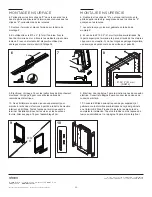
Page 28: ...tage Z au mur 5b Si aucune bande de fourrure ou montant n est disponible utilisez les ancrages en plastique fournis en vous assurant que chaque armoire est soutenue par au moins 3 ancrages Percez un t...

Page 29: ...rra de montaje Z 8 El uso de los 10 X 2 51 mm tornillos suministrados fije la parte superior del armario a la pared a trav s de los mejores clips como se muestra Si no hay ning n esp rrago disponible...

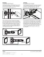
Page 30: ...tion de r glage trois voies La hauteur le niveau c te c te et la profondeur peuvent tre r gl s l aide d un tournevis cruciforme 2 Avec la charni re l g rement ferm e vous pouvez acc der la vis du mili...

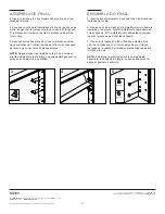
Page 31: ...ntes NOTE Ne pas stocker les objets dans la zone de l armoire directement derri re la charni re que des dommages peut se produire au Cabinet ou des articles ASSEMBLAGE FINAL SS672 SS134 3 4 5 12 SS131...

Page 32: ...ERN no es responsable de los costos de la instalaci n La garant a est anulada si el producto se da a durante el transporte o si el da o o la falla son causados por el abuso el uso incorrecto el uso an...

Reviews: