12
Part no. CB-209-1332 05/05/20
Vitality Cabinet
© 2020 Robern, Inc. 701 N. Wilson Ave. Bristol, PA 19007 U.S.A.
800.877.2376
www.robern.com
Installation instructions
SURFACE MOUNTING
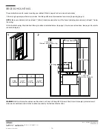
All parts required for surface mounting are included in the optional Surface Mount Kit (see page 4). These instructions are for surface
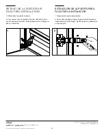
mounting. Refer to page 6 for door removal instructions.
1. It is strongly recommended that the wall be framed behind the drywall or tile.
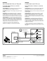
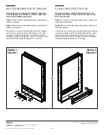
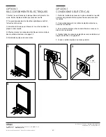
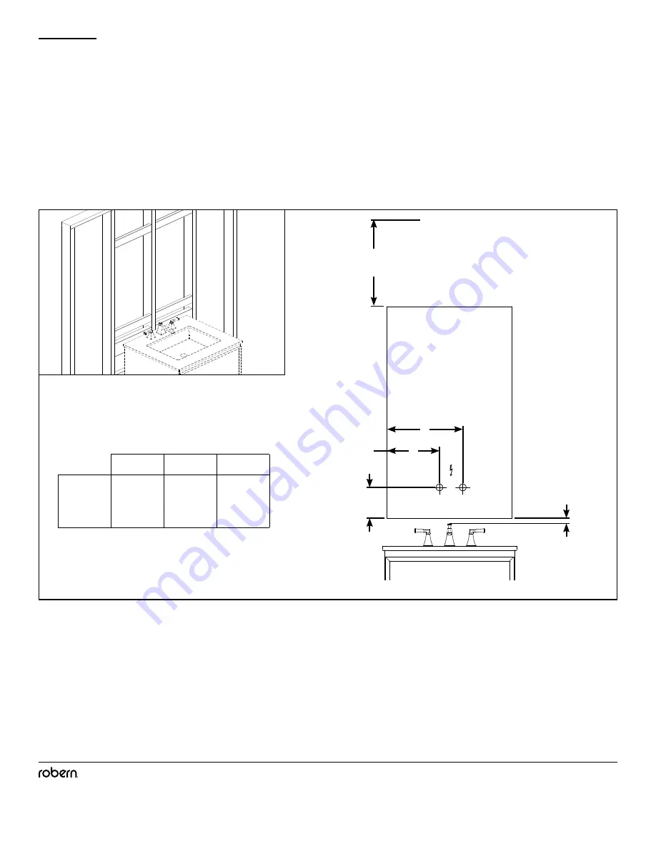
2. Electrical field wiring: Electrical feed through location is indicated below. See page 5 for wire access locations.
NOTE:
Make sure cabinet door has at least 1” (25mm) clearance above the top of the faucet (including drain stop) and at least 1” below
the ceiling.
2
1
Field Wiring
1" (25.4 mm)
Minimum door to faucet
1" (25.4 mm)
Minimum from finished ceiling
B
C
A
A
B
C
YC24
Cabinet
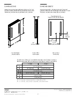
9-1/2"
(248 mm)
5-3/4"
(146 mm)
14-3/8"
(365 mm)
WARNING:
An Electrical option cabinet must be wired to a Class A 20 Amp GFCI (Ground Fault Circuit Interrupter) protected circuit
when used in bathrooms and all other locations required by the National Electric Code.

