6
Part no. CB-209-1332 05/05/20
Vitality Cabinet
© 2020 Robern, Inc. 701 N. Wilson Ave. Bristol, PA 19007 U.S.A.
800.877.2376
www.robern.com
Installation instructions
REMOVING THE DOOR FOR EASE OF INSTALLATION
SECTION 2 - ELECTRIC CONNECTIONS
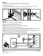
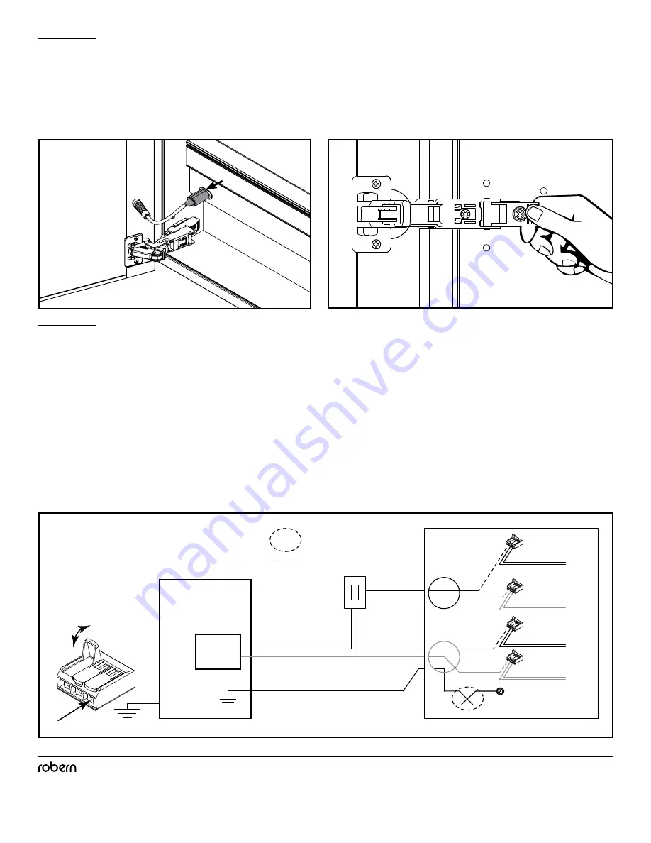
1. Unplug the door from the cabinet.
2. While supporting the door, pinch the release clip at the rear of each hinge, as shown. Set the door aside in a safe place.
NOTE:
The cardboard sleeve attached to the door protects the edges of the door during installation.
2
1
CIRCUIT BREAKER
WHITE
GROUND
BLACK
WHITE
GROUND
BLACK
FIELD CONNECTION
120VAC
20A GFI
DIMMER
LINE/BLACK
LINE/RED
NEUTRAL/WHITE
NEUTRAL/WHITE
3
All wiring should be done by a qualified licensed electrician.
WARNING:
To reduce the risk of electrical shock, shut off power before wiring the cabinet.
CAUTION:
Required 120 VAC Class A 20 Amp GFI protected circuit.
CAUTION:
This product must be connected to a grounded, metal permanent wiring system or an equipment-grounding conductor must
be run with the circuit conductors and connected to the equipment grounding terminal or lead on the product.
WARNING:
An Electrical option cabinet must be wired to a Class A 20 Amp GFCI (Ground Fault Circuit Interrupter) protected circuit
when used in bathrooms and all other locations required by the National Electric Code.
3. Make field connections as per wiring diagram for the electrical option being installed.

