Combat
®
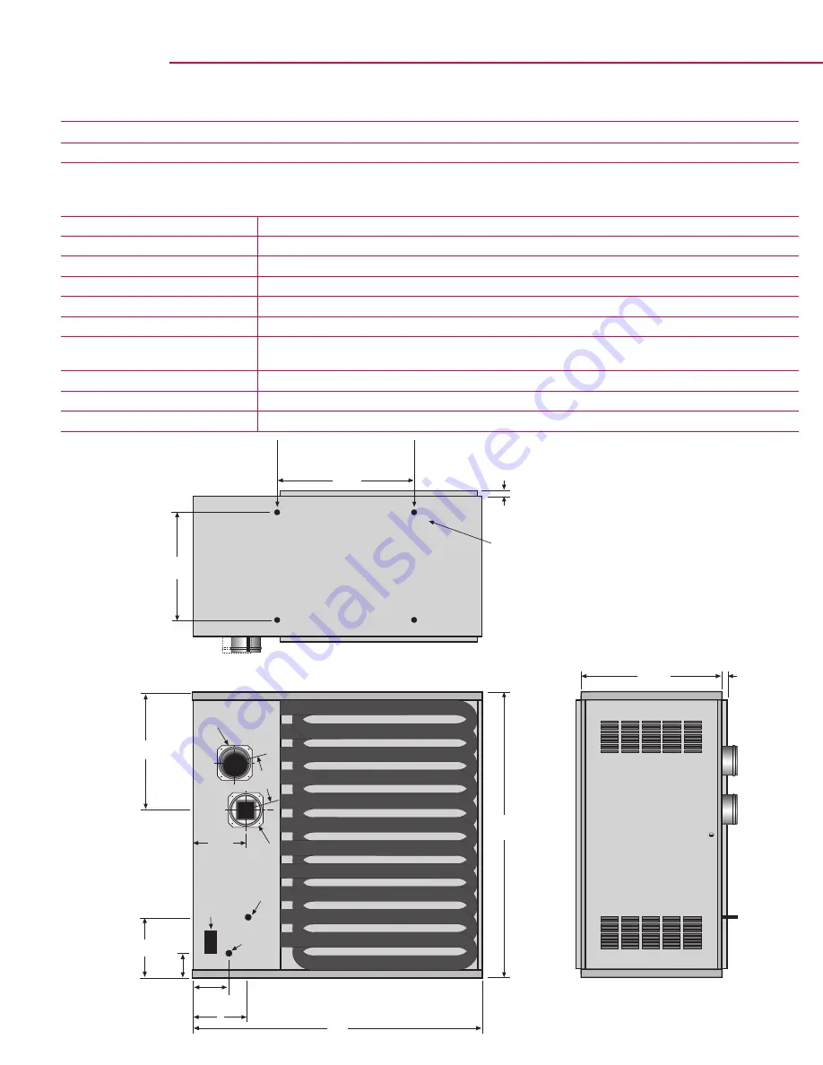
UHD[S] 150 - UHD[S] 400 Clearances and Dimension Data
Dimension Data - Standard UHD[S] Range (Models 150 - 400)
Model
150
175
200
225
250
300
350
400
'A' Width
[in]
43
43
43
43
43
50
50
50
'B' Height
[in]
27
27
35.25
35.25
35.25
43.5
43.5
43.5
'C' Duct Connectors
[in]
1.25
1.25
1.25
1.25
1.25
1.25
1.25
1.25
'D' Support Spacing
[in]
17.6
17.6
17.6
17.6
17.6
24.7
24.7
24.7
'F' Center of Flue
[in]
9.5
9.5
17
17
17
13.6
13.6
13.6
'G' Flue Center to
Air Intake Center
[in]
6
6
6
6
6
7
7
7
'H' Position of Flue
[in]
4.5
4.5
4.75
4.75
4.75
4.9
4.9
4.9
'J' Gas Inlet Position
[in]
5.9
5.9
5.9
5.9
5.9
8.7
8.7
8.7
'K' Electrical Supply Position
[in]
3.4
3.4
3.4
3.4
3.4
6.2
6.2
6.2
K
B
C
25.5”
A
J
2.4”
6.5”
4 x 3/8” Captive Nuts Provided
C
F
D
19.4”
Support
Centers
Rear View
End View
G
H
Top View
Heater must be supported
at these points from above
or below.
Electrical
Supply
Air Intake
(UHDS only)
Flue
Thermostat
Connection
Gas
Supply
Clearances to Combustibles - Low Profile UHD[S] Range (Models 75 - 125)
Above Heater
Below Heater
To Side of Heater
Access Side Door
To Flue
6"
6"
6"
31" Access Clearance
2"

![Preview for 1 page of Roberts Gorden Combat UHD[S] 150-400 Specifications](http://thumbs.mh-extra.com/thumbs/roberts-gorden/combat-uhd-s-150-400/combat-uhd-s-150-400_specifications_1469644-1.webp)
![Preview for 2 page of Roberts Gorden Combat UHD[S] 150-400 Specifications](http://thumbs.mh-extra.com/thumbs/roberts-gorden/combat-uhd-s-150-400/combat-uhd-s-150-400_specifications_1469644-2.webp)
![Preview for 3 page of Roberts Gorden Combat UHD[S] 150-400 Specifications](http://thumbs.mh-extra.com/thumbs/roberts-gorden/combat-uhd-s-150-400/combat-uhd-s-150-400_specifications_1469644-3.webp)
![Preview for 4 page of Roberts Gorden Combat UHD[S] 150-400 Specifications](http://thumbs.mh-extra.com/thumbs/roberts-gorden/combat-uhd-s-150-400/combat-uhd-s-150-400_specifications_1469644-4.webp)


