SECTION 15: R
EPLACEMENT
P
ARTS
51 of 57
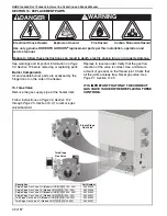
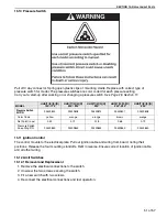
15.10 Pressure Switch
P
u
ll off 3
w
ay connector. Spring open plastic clips of mo
u
nting cradle. Replace
w
ith correct type of
press
u
re s
w
itch for model. The press
u
re s
w
itches are color coded for each press
u
re setting.
Carry o
u
t a start-
u
p after
w
orking on or changing a press
u
re s
w
itch.
See Page 28, Section 11
.
15.11 I
g
nition Control
The control mo
u
nts to the electrical plate. P
u
ll o
u
t ignition cable and
w
iring from board, noting their
positions. Release the fo
u
r mo
u
nting standoffs. Refit in reverse. Ens
u
re correct location of ignition cable
and all other
w
iring.
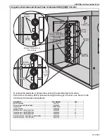
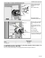
15.12 Limit Switches
15.12.1 Removal and Replacement
1. Remove the electrical connections to the s
w
itch.
2. Unscre
w
the t
w
o scre
w
s sec
u
ring the s
w
itch.
3. Fit a ne
w
s
w
itch
w
ith t
w
o scre
w
s.
4. Reconnect the electrical connections and test operation.
MODEL
UHD[T][X][S][R]
150 - 175
UHD[T][X][S][R]
200 - 225
UHD[T][X][S][R]
250
UHD[T][X][S][R]
300 - 350
UHD[T][X][S][R]
400
Pressure Switch
Kit P/N
90439802
90439808
90439812
90439807
90439808
Color Code
yello
w
orange
orange
bro
w
n
orange
Set Point (in
w
c)
0.32
0.79
0.18
0.68
0.79
Press
u
re S
w
itch
Snap Ring P/N
90439850
90439850
90439850
90439850
90439850
Summary of Contents for Combat UHD-Series
Page 2: ......
Page 4: ......
Page 8: ......
Page 46: ...UHD STANDARD DUCT FURNACE INSTALLATION OPERATION AND SERVICE MANUAL 38 of 57 14 1 General ...
Page 64: ...UHD STANDARD DUCT FURNACE INSTALLATION OPERATION AND SERVICE MANUAL 56 of 57 ...
Page 66: ......
Page 67: ......
Page 68: ......
Page 69: ......
Page 70: ......


