CRV-S
ERIES
I
NSTALLATION
, O
PERATION
AND
S
ERVICE
M
ANUAL
4
NOTE:
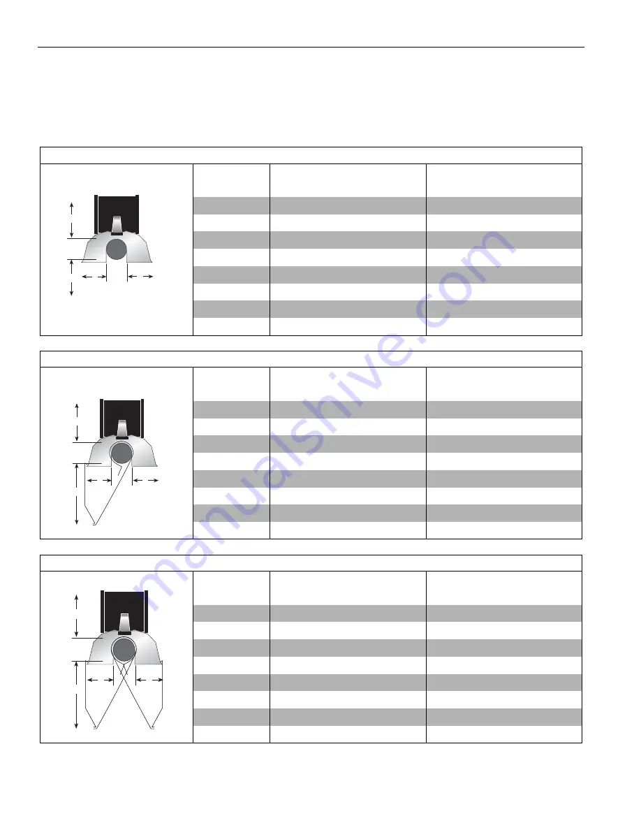
1. All dimensions are from the surfaces of all tubes, couplings, elbows, tees and crosses.
2. Clearances B, C and D can be reduced by 50% after 25' (7.5 m) of tubing downstream from
where the combustion chamber and the tube connect.
*
Protective Grille clearances are the same as Standard Reflector.
.
FIGURE 1: STANDARD REFLECTOR
(inches)
(centimeters)
Model
A
B
C
D
A
B
C
D
CRV-B-2
4
20
48
20
11
51
122
51
CRV-B-4
4
20
48
20
11
51
122
51
CRV-B-6
4
20
48
20
11
51
122
51
CRV-B-8
4
20
48
20
11
51
122
51
CRV-B-9
4
36
60
36
11
92
153
92
CRV-B-10
4
36
60
36
11
92
153
92
CRV-B-12
4
36
60
36
11
92
153
92
CRV-B-12A
4
36
60
36
11
92
153
92
B
C
D
A
FIGURE 2: ONE SIDE REFLECTOR
(inches)
(centimeters)
Model
A
B
C
D
A
B
C
D
CRV-B-2
4
12
56
20
11
31
143
51
CRV-B-4
4
12
56
20
11
31
143
51
CRV-B-6
4
12
56
20
11
31
143
51
CRV-B-8
4
12
56
20
11
31
143
51
CRV-B-9
4
12
60
42
11
31
153
107
CRV-B-10
4
12
60
42
11
31
153
107
CRV-B-12
4
12
60
42
11
31
153
107
CRV-B-12A
4
12
60
42
11
31
153
107
A
B
C
D
FIGURE 3: TWO SIDE REFLECTORS
(inches)
(centimeters)
Model
A
B
C
D
A
B
C
D
CRV-B-2
4
12
56
12
11
31
143
31
CRV-B-4
4
12
56
12
11
31
143
31
CRV-B-6
4
12
56
12
11
31
143
31
CRV-B-8
4
12
56
12
11
31
143
31
CRV-B-9
4
12
60
12
11
31
153
31
CRV-B-10
4
12
60
12
11
31
153
31
CRV-B-12
4
12
60
12
11
31
153
31
CRV-B-12A
4
12
60
12
11
31
153
31
A
B
C
D


