


CRV-S
ERIES
I
NSTALLATION
, O
PERATION
AND
S
ERVICE
M
ANUAL
46
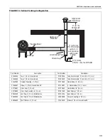
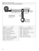
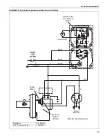
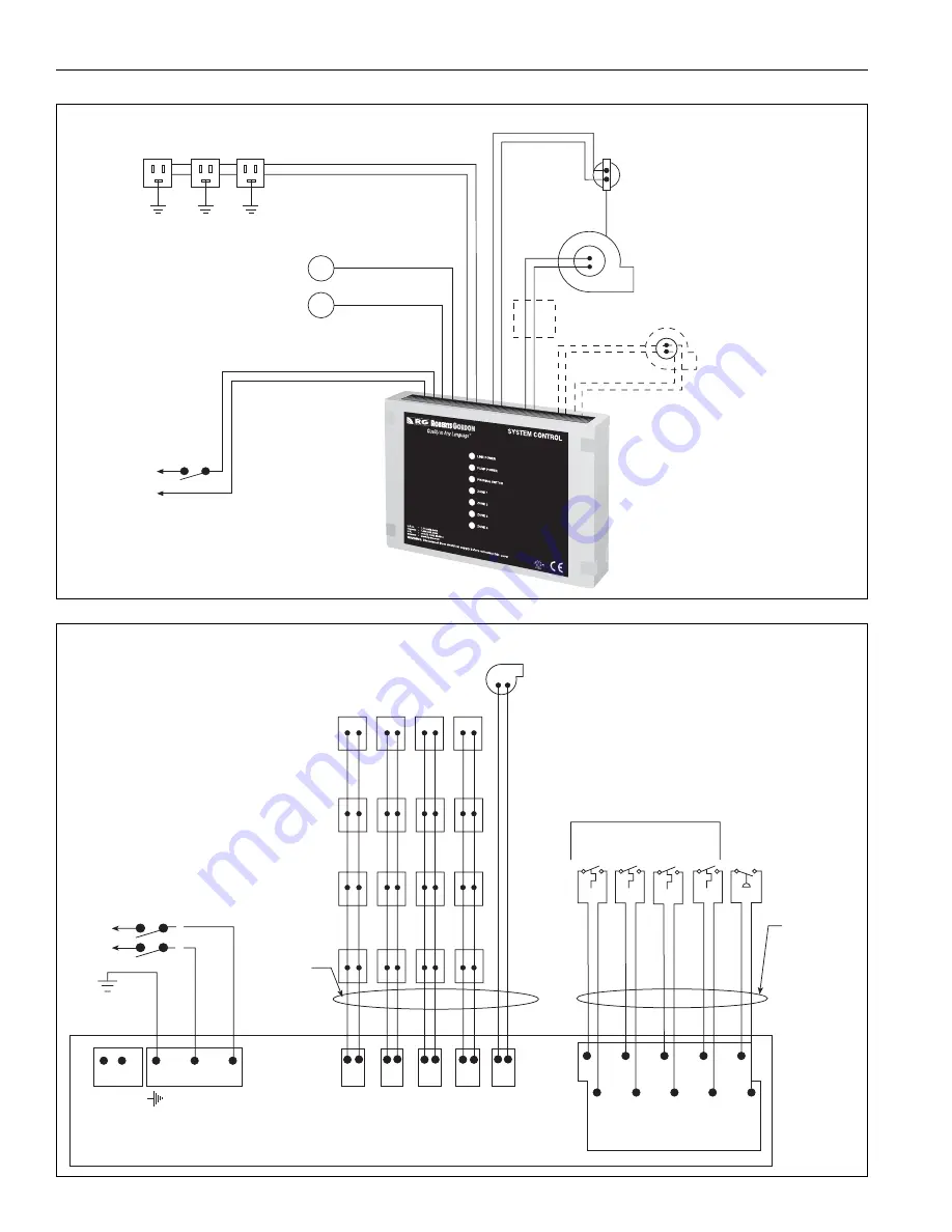
FIGURE 29: General System Wiring
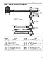
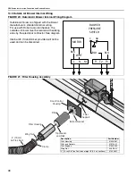
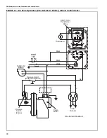
FIGURE 30: External Wiring Diagram EP-100 and EP-201 120 V 1 Ø Pump
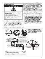
Burner Receptacles
4 Zone Max
120 Vac
Maximum 20 Amps Total
Thermostats
Outside
Air Supply
Blower Motor
and Pressure
Switch
Pump Motor
115 Vac Operation
(230 Vac Operation-
separate power circuit
required for EP-203 or
EP-300 series pumps)
Pressure
Switch
Motor Starter
(Needed for EP-203 and EP-300 Series Pump)
L
120 V
1 Ø
60 Hz
N
System
C
ontrol
C
T
1
C
C
C
C
T3
T2
T
4
PS
12 Vdc
120 V
1 Ø
60 Hz
Ground
G
L
N
Gr
o
und
120 V
1 Ø
60 Hz
PU
M
P
N L
Z1
Z
2
Z
3
Z4
N
N
N
N
L
L
L
L
A
ll
b
urners must
b
e
c
o
nnected t
o
Gr
o
und
(
N
o
t sh
ow
n
)
Z
o
ne 1 Z
o
ne
2
Z
o
ne
3
Z
o
ne 4
Pump
L
N
L
ow
v
ol
ta
g
e therm
o
stats
lo
cated in heated z
o
ne
Z
o
ne
1
Z
o
ne
2
Z
o
ne
4
Z
o
ne
3
Pressure s
w
itch
lo
cated at pump


