SECTION 7: H
EATER
I
NSTALLATION
21 of 83
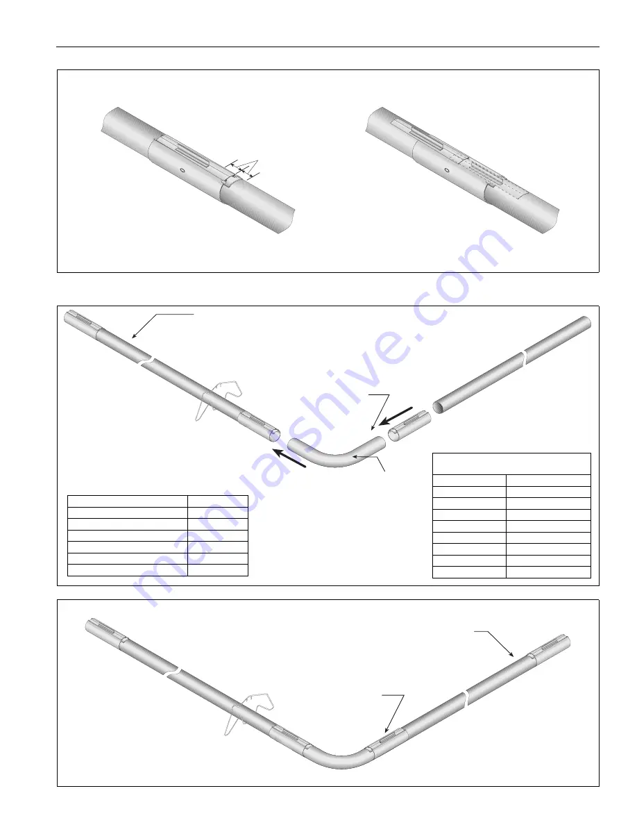
Step 7.2.1 Couplin
g
and Tube Assembly (Continued)
7.3 Elbow Packa
g
e Confi
g
uration
Step 7.3.1 Elbow Installation
Step 7.3.2 Elbow Installation
Incorrect slide bar
position
Correct slide bar
dimensions
± 2" (5 cm)
Drive slide bar until tight.
End of slide bar should be
within tolerance listed below.
Repeat
Step 7.2
, A - D until all tubes are assembled.
NOTE: If couplin
g
is not ti
g
ht, loss of vacuum can occur.
Ti
g
hten slide bar as shown below.
T
u
b
e
9
0°
E
lbow
C
o
up
l
in
g
Description
Part Number
Elbow Packa
g
e
0271
8
702
90° Elbo
w
01335801
Co
u
pling
01312700
Reflector End Cap
02750800
Reflector Joint Piece
02750900
U-Clip Package
91107720
Minimum Distance Re
q
uired Between
Burner and Elbow
Model
Minimum Distance
CRVB-2
5' (1.5 m)
CRVB-4
5' (1.5 m)
CRVB-6
10' (3 m)
CRVB-8
10' (3 m)
CRVB-9
10' (3 m)
CRVB-10
15' (4.5 m)
CRVB-12A
15' (4.5 m)
CRVB-12
15' (4.5 m)
T
u
b
e
C
o
up
l
in
g
Summary of Contents for CoRayVac CRV-B-10
Page 2: ......
Page 4: ......
Page 6: ......
Page 71: ...SECTION 13 STARTING THE SYSTEM 65 of 83 FIGURE 42 Vacuum Reading ...
Page 81: ...SECTION17 TROUBLESHOOTING 75 of 83 17 1 Troubleshooting Flow Chart ...
Page 90: ......
Page 91: ......
Page 92: ......
Page 93: ......
Page 94: ......


