CRV-S
ERIES
I
NSTALLATION
, O
PERATION
AND
S
ERVICE
M
ANUAL
44 of 83
FIGURE 22: Duct Sizin
g
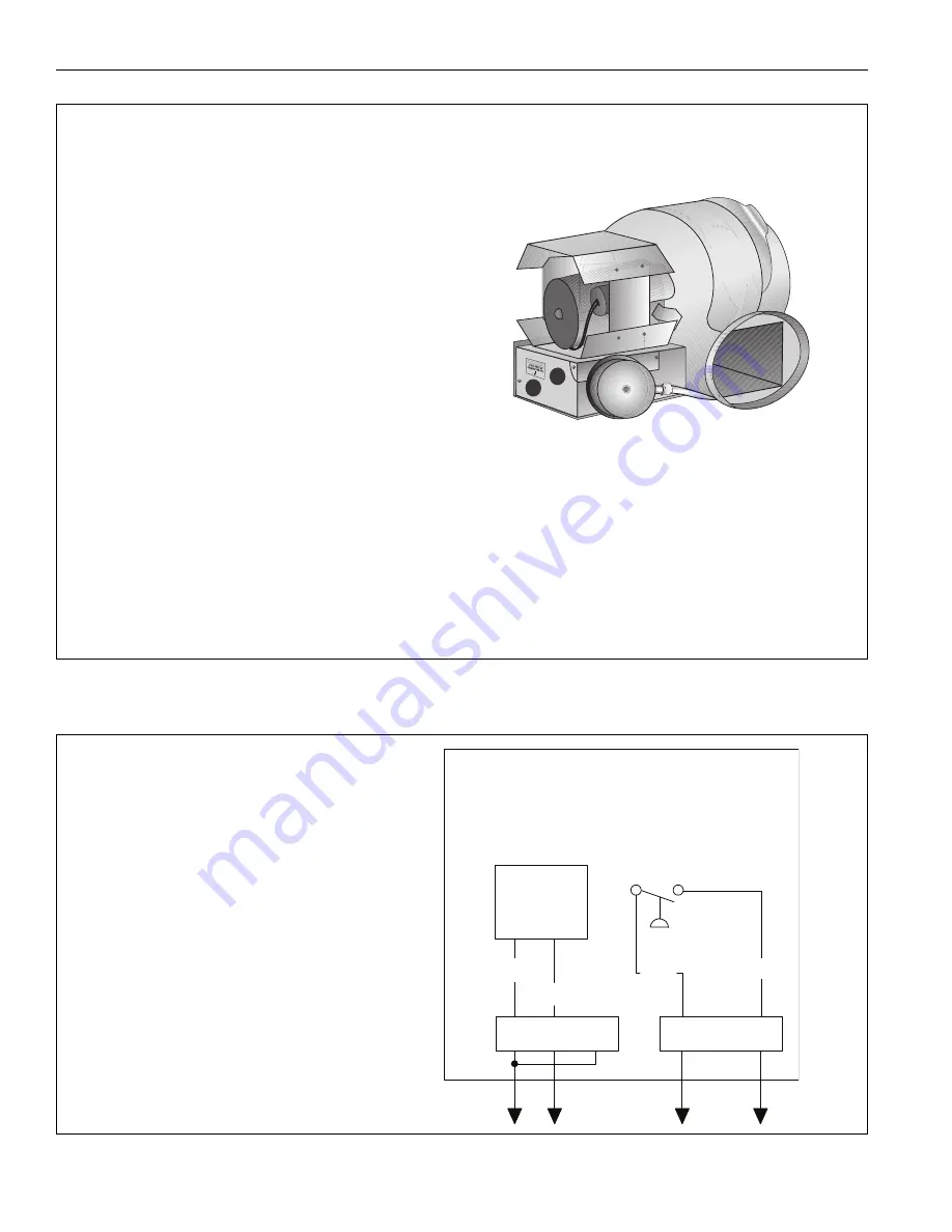
10.3 Outside Air Blower Internal Wirin
g
FIGURE 23: Outside Air Blower Internal Wirin
g
Dia
g
ram
Outside Air System Desi
g
n Re
q
uirements:
Blower Performance (90707501K):
112 Flow Units
One o
u
tside air blo
w
er is req
u
ired per each EP-100 or
EP-200 series p
u
mp and t
w
o o
u
tside air blo
w
ers may
be req
u
ired for each EP-300 series p
u
mp. O
u
tside air
blo
w
ers cannot be shared bet
w
een t
w
o separate CRV-
Series systems.
Duct Desi
g
n Rules:
- System sho
u
ld be designed so that the blo
w
er is
positioned closest to the highest flo
w
req
u
irements (end
v
ents).
- When a d
u
ct is carrying more than 40 flo
w
u
nits, it
m
u
st be at least 6" (15 cm) diameter.
Press
u
rized Systems
- 6" (15 cm) diameter d
u
ct m
u
st not exceed 120'
(36 m) total per system.
- 4" (10 cm) diameter d
u
ct m
u
st not exceed 120'
(36 m) per radiant branch.
Non Press
u
rized
- 6" (15 cm) diameter d
u
ct m
u
st not exceed 90'
(27 m) maxim
u
m 100 flo
w
u
nits
- 4" (10 cm) diameter d
u
ct m
u
st not exceed 90'
(27 m)
- Elbo
w
s are eq
u
i
v
alent to 10' (3 m) of d
u
ct length.
L
MOTOR
M
N
BLK
W
HT
T1
T3
T2
C
N
O
BLU
BLU
BLO
W
ER
PRESSURE
S
W
ITCH
The o
u
tside air blo
w
er is shipped
w
ith the
blo
w
er man
u
fact
u
rer’s standard internal
w
iring.
For
u
se
w
ith ROBERTS GORDON
®
heaters,
the o
u
tside air blo
w
er m
u
st be re
w
ired
w
ith
existing
w
ires by the electrical contractor. See
diagram.
NOTE: The internal 24 V relay provided will
not be used and can be discarded.
Summary of Contents for CoRayVac CRV-B-10
Page 2: ......
Page 4: ......
Page 6: ......
Page 71: ...SECTION 13 STARTING THE SYSTEM 65 of 83 FIGURE 42 Vacuum Reading ...
Page 81: ...SECTION17 TROUBLESHOOTING 75 of 83 17 1 Troubleshooting Flow Chart ...
Page 90: ......
Page 91: ......
Page 92: ......
Page 93: ......
Page 94: ......


