


SECTION 12: C
ONTROL
M
ETHODS
51 of 83
12.3.4 Cable Re
q
uirement
Table 3
,
on
Page 51,
lists
w
iring types, sizes and
distances for mod
u
lating thermostat comm
u
nication.
Power Re
q
uirement
Programmable thermostats req
u
ires 24
v
olt, AC
po
w
er.
12.3.5 Se
q
uence of Operation
Depending on the space temperat
u
re, the thermostat
w
ill control the heat o
u
tp
u
t based on demand signal
comm
u
nicated from the thermostat program. The
thermostat
w
ill close contact on the transformer relay
(P/N 90417600K). The VFD r
u
n command is
energized by the transformer relay. When the VFD
energizes the p
u
mp and the
v
ac
uu
m has been
established, the press
u
re s
w
itch
w
ill close and
energize the b
u
rners. At high heat, a demand signal
w
ill t
u
rn the p
u
mp speed to a maxim
u
m freq
u
ency
and b
u
rner(s) ON at maxim
u
m firing rate. As the
space temperat
u
re gets closer to the set point, the
thermostat program
w
ill slo
w
the p
u
mp speed and
b
u
rner(s) firing rate do
w
n
u
ntil the room temperat
u
re
reaches the thermostat set point.
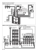
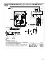
NOTE:
To obtain Analog 0-10VDC signal, connect as sho
w
n
on Page 61, Figure 39
and set standard speed
so
u
rce (parameter 05 inside VFD men
u
) to 03.
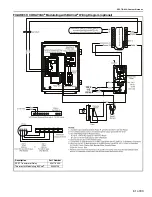
12.3.6 Analo
g
Si
g
nal
An Analog Signal 2-10 Vdc (
w
ith 500 ohm resistor) or
4-20 mA o
u
tp
u
t from a mod
u
lating thermostat
controls the ROBERTS GORDON
®
VFD. The VFD
s
u
pplies a
v
ariable freq
u
ency o
u
tp
u
t signal to the
p
u
mp that
w
ill
v
ary based on the signal from the
mod
u
lating thermostat.
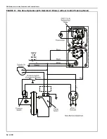
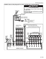
The ROBERTS GORDON
®
CORAYVAC
®
w
ith
mod
u
lating thermostat
w
iring diagram is sho
w
n
on
Page 59, Figure 37
. When the temperat
u
re falls
belo
w
the setpoint, the mod
u
lating thermostat
w
ill
generate a demand signal to the VFD. The VFD
w
ill
o
u
tp
u
t a signal to the p
u
mp to r
u
n at the desired
heater(s) firing rate. There are t
w
o means to set
u
p
the analog signal from the mod
u
lating thermostat to
the VFD (
See Page 51, Figure 29
):
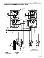
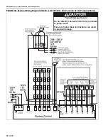
1. To obtain 4-20 mA signal, connect as sho
w
n
on
Page 60, Figure 38
and set standard speed
so
u
rce (parameter 05 inside VFD men
u
) to 04.
2. To obtain 2-10 Vdc (
w
ith 500 ohm resistor)
signal, connect as sho
w
n
on Page 59, Figure 37
and set standard speed so
u
rce (parameter 05
inside VFD men
u
) to 03.
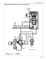
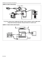
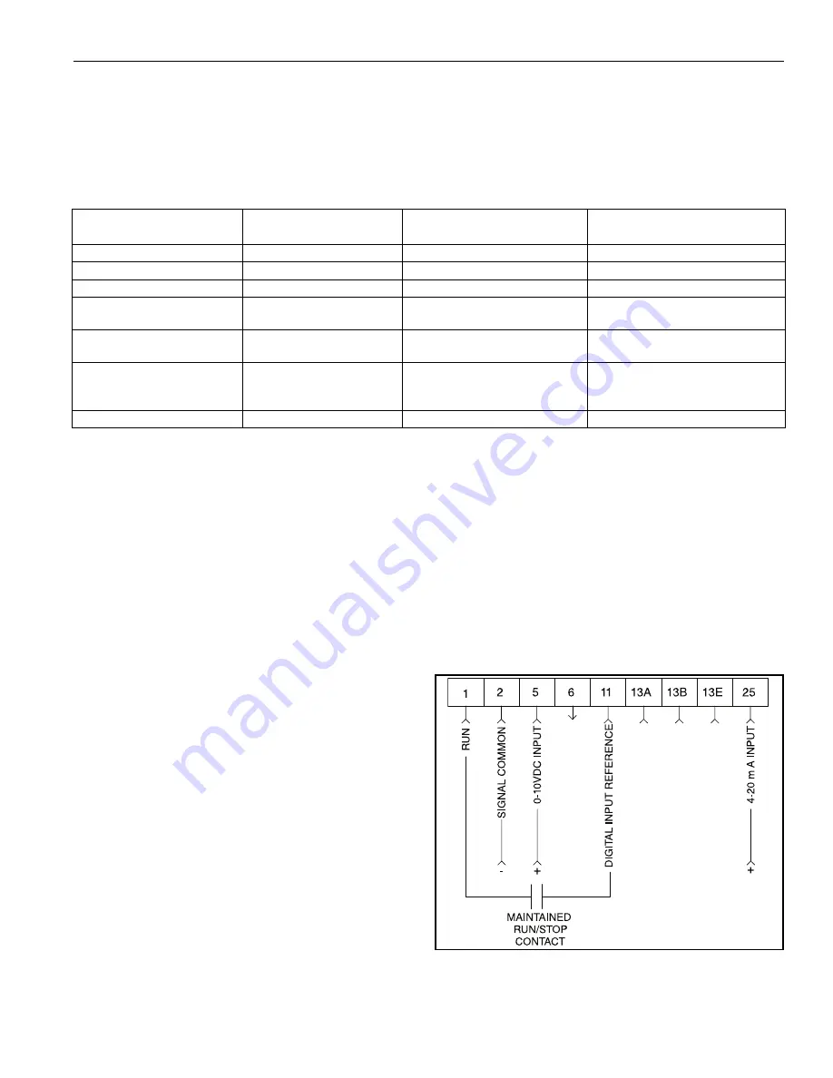
FIGURE 29: VFD Terminal Strip
As the p
u
mp recei
v
es the analog signal from the
VFD, the heater(s) mod
u
late to the corresponding
firing rate. As sensed air temperat
u
re rises closer to
Table 3: Modulatin
g
Thermostat Cable Re
q
uirements
Wire Function
Recommended Wire Size
(Minimum)
Specification or
Re
q
uirement
Distance (Maximum)
Digital O
u
tp
u
ts
18 AWG (0.75 sq mm)
Standard thermostat
w
ire
1000 ft (304 m)
Mod
u
lating O
u
tp
u
ts
18 AWG (0.75 sq mm)
1 pair
500 ft (152 m)
O
u
tdoor Air Temperat
u
re Sensor 18 AWG (0.75 sq mm)
1 pair
500 ft (152 m)
Remote Sensor
18 to 22 AWG
(0.75 to 0.34 sq mm)
T
w
isted pair
w
ire
1000 ft (304 m)
Po
w
er Wiring
18 to 14 AWG
( 0.75to 2.0 sq mm)
NEC Class II 140ºF (60°C )
Limited by line-loss effects on po
w
er
cons
u
mption.
LonWorks
®
(P/N 90424104 only) 18 AWG
(0.75 sq mm) nonshielded
1 pair
Refer to E-b
u
s Wiring G
u
ide 74-2865
for maxim
u
m length and generic cable
specifications.
MS/TP (P/N 90425109)
18 AWG (0.75 sq mm) Shield Belden cable #82760 or eq
u
i
v
alent
Refer to Thermostat Installation G
u
ide
Summary of Contents for CoRayVac CRV-B-10
Page 2: ......
Page 4: ......
Page 6: ......
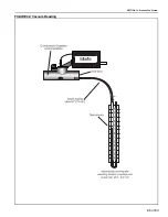
Page 71: ...SECTION 13 STARTING THE SYSTEM 65 of 83 FIGURE 42 Vacuum Reading ...
Page 81: ...SECTION17 TROUBLESHOOTING 75 of 83 17 1 Troubleshooting Flow Chart ...
Page 90: ......
Page 91: ......
Page 92: ......
Page 93: ......
Page 94: ......


