CRV-S
ERIES
I
NSTALLATION
, O
PERATION
AND
S
ERVICE
M
ANUAL
64 of 83
2. Allo
w
at least ½ ho
u
r operation for temperat
u
re
to normalize, then check system
v
ac
uu
m bal-
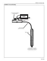
ance. Vac
uu
m can be meas
u
red by inserting a
manometer hose into the end
v
ent as sho
w
n
on
Page 65, Figure 42
. Normal end
v
ent
v
ac
uu
m
sho
u
ld be set at approximately 2.5''
w
c to 3.0''
w
c
(hot).
Vac
uu
m adj
u
stments are made by means of the
damper in the p
u
mp inlet and the adj
u
stable
damper co
u
pling(s) in the system. Check the
v
ac
uu
m at all end
v
ents and then adj
u
st the
damper co
u
pling to obtain eq
u
al
v
ac
uu
m
readings of 2.5''
w
c to 3.0''
w
c. If end
v
ent
v
ac
uu
m exceeds 3.0"
w
c, adj
u
st the p
u
mp inlet
damper
u
ntil
v
ac
uu
m readings are 2.5''
w
c to
3.0''
w
c.
With systems designed to operate at maxim
u
m
v
ac
uu
m, it may not be possible to obtain
v
ac
uu
m differential readings at or slightly abo
v
e
2.5''
w
c. If so, adj
u
st the damper co
u
plings to
maxim
u
m b
u
t eq
u
al
v
ac
uu
m reading. Be s
u
re to
lock all dampers sec
u
rely after adj
u
stment.
3. Reset temperat
u
re setpoints to desired room
temperat
u
re.
4. If heat is not req
u
ired, t
u
rn off main s
w
itch and
close the main gas
v
al
v
e.
Summary of Contents for CoRayVac CRV-B-10
Page 2: ......
Page 4: ......
Page 6: ......
Page 71: ...SECTION 13 STARTING THE SYSTEM 65 of 83 FIGURE 42 Vacuum Reading ...
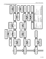
Page 81: ...SECTION17 TROUBLESHOOTING 75 of 83 17 1 Troubleshooting Flow Chart ...
Page 90: ......
Page 91: ......
Page 92: ......
Page 93: ......
Page 94: ......


