CRV-S
ERIES
I
NSTALLATION
, O
PERATION
AND
S
ERVICE
M
ANUAL
68 of 83
SECTION 15: COMMISSIONING THE CORAYVAC
®
MODULATING SYSTEM
NOTE:
Before starting the commissioning proced
u
re,
all the
w
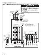
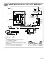
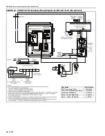
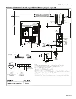
iring of the ROBERTS GORDON
®
ULTRAVAC
™
control boards, relay boards, mod
u
lat-
ing thermostats, p
u
mps and VFD m
u
st be com-
pleted. The comm
u
nication connection m
u
st be
made to the controller, mod
u
lating thermostat and
b
u
rners. The ROBERTS GORDON
®
ULTRAVAC
™
soft
w
are m
u
st be installed on the PC.
It is important to
u
nderstand that the freq
u
ency that
the VFD r
u
ns the motor at, determines the speed of
the impeller in the p
u
mp. Variation of the impeller
speed
w
ill increase or decrease
v
ac
uu
m in the sys-
tem. The follo
w
ing proced
u
re
w
ill help yo
u
set mini-
m
u
m and maxim
u
m VFD freq
u
ency settings to
achie
v
e proper
v
ac
uu
m in the system.
15.1 Settin
g
The CORAYVAC
®
End Burner
Vacuum
15.1.1 ROBERTS GORDON
®
ULTRAVAC
™
For complete ROBERTS GORDON
®
ULTRAVAC
™
installation please refer to the ROBERTS GORDON
®
ULTRAVAC
™
Installation, Operation and Ser
v
ice
Man
u
al (P/N 10081601NA), latest edition.
15.1.2 Modulatin
g
Thermostat
T
u
rn on po
w
er to the VFD and transformer relay; this
sho
u
ld energize the mod
u
lating thermostat. Set the
thermostat to "call for heat" as described in the
accompanying instr
u
ctions for the mod
u
lating
thermostat.
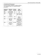
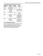
See Page 66, Section 14
for setting
u
p
the VFD.
15.2 Adjustin
g
the Variable Fre
q
uency Drive
15.2.1 Maximum Si
g
nal Speed
The p
u
mp sho
u
ld be r
u
nning and the b
u
rners sho
u
ld
light
w
ithin 60 seconds. At the VFD,
v
erify the
n
u
mber displayed on the LCD screen is "60.0" If it is
lo
w
er than 60.0, hit the "
u
p" arro
w
b
u
tton on the VFD
u
ntil the n
u
mber reads 60.0 Let the b
u
rners fire for
approximately 20-30 min
u
tes to
w
arm
u
p the system.
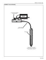
Using a manometer, check the end
v
ent
v
ac
uu
m in
each zone (each branch of b
u
rners).
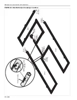
See Page 70,
Figure 43
.
If the lo
w
est end
v
ent
v
ac
uu
m reading is abo
v
e 3.0"
w
c, red
u
ce the
v
ac
uu
m p
u
mp speed. Generally, the
lo
w
est end
v
ent
v
ac
uu
m reading is on the longest
branch of the system. Use the do
w
n arro
w
b
u
tton on
the VFD to red
u
ce the freq
u
ency of the o
u
tp
u
t signal
to the p
u
mp, th
u
s red
u
cing the p
u
mp speed and
lo
w
ering the end
v
ent
v
ac
uu
m reading. Contin
u
e to
red
u
ce the freq
u
ency
u
ntil the end
v
ent
v
ac
uu
m
reading is bet
w
een 2.5" - 3.0"
w
c. Make note of this
freq
u
ency setting belo
w
. The freq
u
ency is fo
u
nd on
the VFD’s LCD screen.
2.5" wc - 3.0" wc VFD Fre
q
uency Settin
g
NOTE:
To a
v
oid damage to the p
u
mp motor, do not
adj
u
st the freq
u
ency abo
v
e 60.0 Hz. Verify that the
end
v
ent
v
ac
uu
m readings in the remaining branches
are proper. If necessary, adj
u
st the proper damper
co
u
pling to achie
v
e an end
v
ent
v
ac
uu
m of 2.5" - 3.0"
w
c,
See Page 65, Figure 42
. Damper co
u
plings
sho
u
ld be fo
u
nd near the end of the radiant portion of
the pipe in each branch or
w
here a branch connects
to other branches at a cross or tee.
See Page 70,
Figure 43
.
15.2.2 Minimum Si
g
nal Speed
After setting end
v
ent
v
ac
uu
ms bet
w
een 2.5"
w
c and
3.0"
w
c,
w
hile all the b
u
rners are still operating,
u
se
the do
w
n arro
w
b
u
tton on the VFD to red
u
ce the
freq
u
ency of the o
u
tp
u
t signal to the p
u
mp. Red
u
ce
the freq
u
ency of the VFD
u
ntil the manometer at
each of the end
v
ents reads 1.2"
w
c - 1.5"
w
c. Make
note of this freq
u
ency setting belo
w
. The freq
u
ency is
fo
u
nd on the VFD's LCD screen.
1.0" w.c. - 1.2" wc VFD Fre
q
uency Settin
g
Record Fre
q
uency Settin
g
Here:
Record Fre
q
uency Settin
g
Here:
Summary of Contents for CoRayVac CRV-B-10
Page 2: ......
Page 4: ......
Page 6: ......
Page 71: ...SECTION 13 STARTING THE SYSTEM 65 of 83 FIGURE 42 Vacuum Reading ...
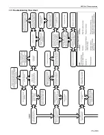
Page 81: ...SECTION17 TROUBLESHOOTING 75 of 83 17 1 Troubleshooting Flow Chart ...
Page 90: ......
Page 91: ......
Page 92: ......
Page 93: ......
Page 94: ......

