SECTION 12: I
NTEGRATION WITH
B
UILDING
M
ANAGEMENT
S
YSTEM
(BMS)
99
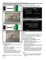
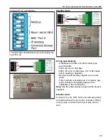
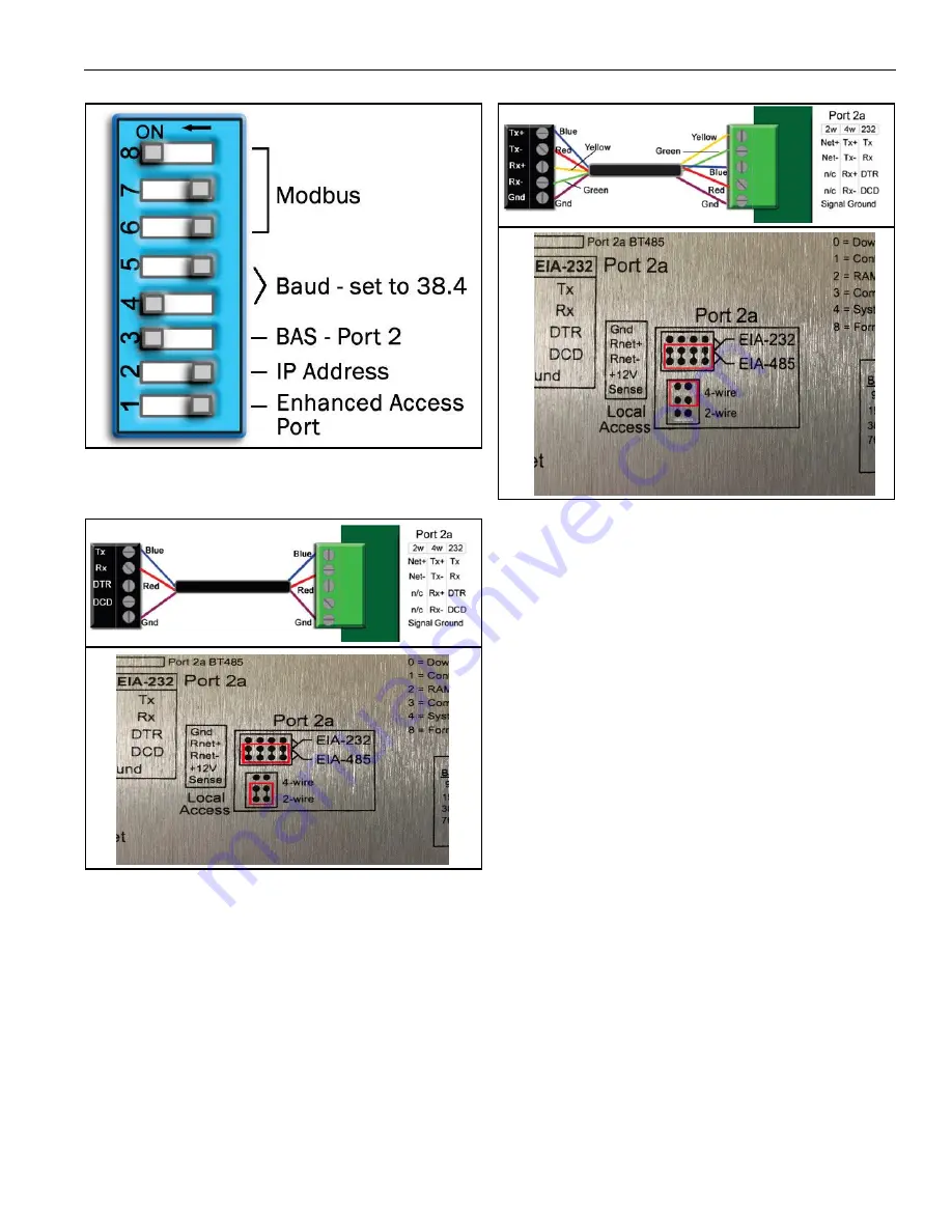
for 38.4k, Port 2, and Modbus.
7. Connect the communications port and jumper wir-
ing to Port 2a.
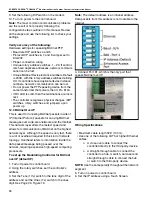
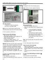
EIA-485, 4-wire
Wiring specifications
• A dedicated 24 AWG to 18 AWG twisted pair
• wire (EIA-485)
• 2000’ (610 m) for 76.8 kbps
• 3000’ (914.4 m) for 9600 bps, 19.2 or 38.4 kbps,
before needing a Repeater
• Devices should be daisy chained and not star
wired
• If the controller is at either end of a network seg-
ment, connect a terminating resistor (P/N
10061018) to the I/O Pro 812u
Note:
Use the same polarity throughout the network
segment.
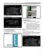
EIA-232, 2-wire
Connect to Tx, Rx, DTR, DCD, and Gnd using three
wire termination with pins 3 and 4 jumpered. Wiring
must go plus-to-minus and minus-to-plus, Gnd-to-
Gnd.
Summary of Contents for CORAYVAC
Page 2: ......
Page 4: ......
Page 69: ...SECTION 8 PROGRAMMING AND TROUBLESHOOTING THE SYSTEM 65 THIS PAGE LEFT INTENTIONALLY BLANK ...
Page 71: ...SECTION 9 TROUBLESHOOTING 67 FIGURE 26 Vacuum pump does not turn on ...
Page 75: ...SECTION 9 TROUBLESHOOTING 71 FIGURE 31 Burner troubleshooting in manual mode ...
Page 77: ...SECTION 9 TROUBLESHOOTING 73 After 45 second prepurge burners do not light continued ...
Page 81: ...SECTION 9 TROUBLESHOOTING 77 FIGURE 36 Air Pressure Switch alarm ...
Page 83: ...SECTION 9 TROUBLESHOOTING 79 FIGURE 38 Repeater troubleshooting ...
Page 85: ...SECTION 9 TROUBLESHOOTING 81 BACnet MS TP troubleshooting continued ...
Page 109: ...SECTION 13 TOUCHSCREEN TREE 105 Touchscreen Tree Overview continued ...
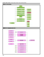
Page 111: ...SECTION 13 TOUCHSCREEN TREE 107 FIGURE 47 Maintenance Unit FIGURE 48 Alarms ...
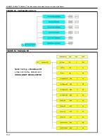
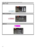
Page 113: ...SECTION 13 TOUCHSCREEN TREE 109 FIGURE 51 Configuration Zones FIGURE 52 Configuration Unit ...
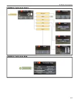
Page 115: ...SECTION 13 TOUCHSCREEN TREE 111 FIGURE 55 Touchscreen System FIGURE 56 Touchscreen Setup ...
Page 118: ...ROBERTS GORDON CORAYVAC MODULATING HEATING CONTROL CONTROLLER INSTALLATION MANUAL 114 ...

