SECTION 12: I
NTEGRATION WITH
B
UILDING
M
ANAGEMENT
S
YSTEM
(BMS)
101
address.
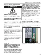
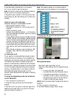
3. Set the Comm Selector DIP Switches 1 - 8 for
baud rate, port number, wiring, and protocol.
4. Set the Comm Selector DIP Switches 4 and 5 for
9600 bps.
Note:
Use the same baud rate for all devices on the
network segment.
5. Set Comm Selector DIP Switch 3 OFF for BAS
Port
6. Set the Comm Selector DIP Switches 6 through 8
for N2.
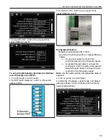
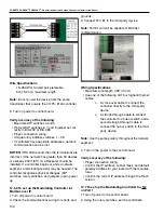
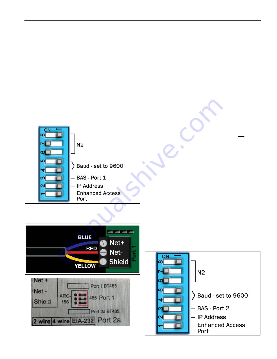
The following example shows the DIP Switches set
for 9600 baud, Port 1, and N2.
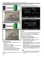
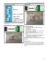
7. Connect the communications wiring to Port 1a.
Connect to Net+, Net- and Gnd
Wiring specifications
• A dedicated 24 AWG to 18 AWG twisted pair wire
(EIA-485)
• 2000’ (610 m) for 76.8 kbps
• 3000’ (914.4 m) for 9600 bps, 19.2 or 38.4 kbps,
before needing a Repeater
• Devices should be daisy chained and not star
wired
• If the controller is at either end of a network seg-
ment, connect a terminating resistor (P/N
10061018) to the I/O Pro 812u
NOTE:
Use the same polarity throughout the
network segment.
7. Turn on power to control board.
To set up the Modulating Controller for N2 on
Port 2a
1. Turn off power to control board.
2. Using the rotary switches, set the controller's
address.
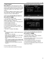
3. Set the Comm Selector DIP Switches 4 and 5 for
9600 bps.
Note:
Use the same baud rate for all devices on the
network segment.
4. Set Comm Selector DIP Switch 3 ON for Port 2.
5. Set the Comm Selector DIP Switches 6 through 8
for N2.
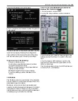
The following example shows the DIP Switches set
for 38.4 kbps baud rate, Port 1, and N2.
Summary of Contents for CORAYVAC
Page 2: ......
Page 4: ......
Page 69: ...SECTION 8 PROGRAMMING AND TROUBLESHOOTING THE SYSTEM 65 THIS PAGE LEFT INTENTIONALLY BLANK ...
Page 71: ...SECTION 9 TROUBLESHOOTING 67 FIGURE 26 Vacuum pump does not turn on ...
Page 75: ...SECTION 9 TROUBLESHOOTING 71 FIGURE 31 Burner troubleshooting in manual mode ...
Page 77: ...SECTION 9 TROUBLESHOOTING 73 After 45 second prepurge burners do not light continued ...
Page 81: ...SECTION 9 TROUBLESHOOTING 77 FIGURE 36 Air Pressure Switch alarm ...
Page 83: ...SECTION 9 TROUBLESHOOTING 79 FIGURE 38 Repeater troubleshooting ...
Page 85: ...SECTION 9 TROUBLESHOOTING 81 BACnet MS TP troubleshooting continued ...
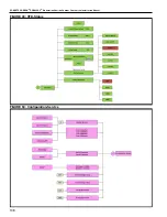
Page 109: ...SECTION 13 TOUCHSCREEN TREE 105 Touchscreen Tree Overview continued ...
Page 111: ...SECTION 13 TOUCHSCREEN TREE 107 FIGURE 47 Maintenance Unit FIGURE 48 Alarms ...
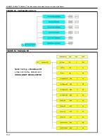
Page 113: ...SECTION 13 TOUCHSCREEN TREE 109 FIGURE 51 Configuration Zones FIGURE 52 Configuration Unit ...
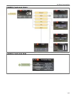
Page 115: ...SECTION 13 TOUCHSCREEN TREE 111 FIGURE 55 Touchscreen System FIGURE 56 Touchscreen Setup ...
Page 118: ...ROBERTS GORDON CORAYVAC MODULATING HEATING CONTROL CONTROLLER INSTALLATION MANUAL 114 ...


