ROBERTS GORDON
®
CORAYVAC
®
M
ODULATING
H
EATING
C
ONTROL
C
ONTROLLER
I
NSTALLATION
M
ANUAL
16
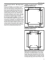
panel over pre-drilled holes and secure control panel
using minimum 5/16" - 18 x 2" bolts and washers (not
supplied).
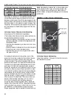
3.3 Cable Requirements:
As per individual building specification for class of
cable to be used. Use copper conductors only. Below
is the recommended cable for the various connec-
tions for CORAYVAC
®
and COMPLETE™ Modulat-
ing Heating Control.
CAUTION:
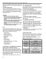
• Separate line and low voltage circuits.
• Do not run line voltage wiring through bottom
section of enclosure that houses control
board.
• Do not run low voltage through top section of
enclosure that houses the relay board.
• Do not run line and low voltage wiring in same
conduit.
• Do not run wiring for vacuum pumps 1 and 2
from VFDs in the same conduit.
Note:
Avoid running communication wires or sensor input
wires next to AC power wires or the controller's relay
output wires. The resulting noise can affect signal
quality. Common sources of noise are:
• Spark igniters
• Radio transmitters
• Variable speed drives
• Electric motors (> 1hp)
• Generators
• Relays
• Transformers
• Induction heaters
• Large contactors (i.e., motor starters)
• Video display devices
• Lamp dimmers
• Fluorescent lights
3.4 CORAYVAC
®
and COMPLETE™ Modulating
Heating Control Installation Materials
Note:
Systems must be electrically grounded in
accordance with the following codes: United States:
Refer to National Electrical Code®, NFPA 70 - latest
revision. Wiring must conform to the most current
National Electrical Code®, local ordinances and any
special diagrams furnished.
Canada: Refer to Canadian Electrical Code, CSA
C22.1 Part 1 - latest revision. Plan accordingly.
3.4.1 Switchable Loads
The controller relays are rated for switching loads no
greater than 6 A. The total added current load for all
4 relays must not exceed 20 A.
3.4.2 Control Programming Details
Controllers are pre-programmed. Can be configured
in the field to any combination of one/two pumps,
four heating zones, single stage or modulating uni-
tary heaters, CORAYVAC
®
or VANTAGE
®
Multiburner
systems.
• Control Power Supply Connection
The power connection should be made with cable,
size 12 AWG.
• Four Digital Output (Relays)
The control connection for load of each individual
relay should be made with cable, size 14 AWG.
• Modulation Signal from Control Board (UO 5-8)
0-10V control signal from outputs UO 5-8 on the
modulation controller to modulating heaters, should
be made with cable, size 18 AWG.
• Digital Input
The wiring connection for the pressure switch should
be unshielded cable, size 18 AWG.
• Indoor Sensor Cable
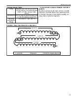
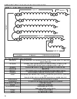
Rnet communication wires should be connected in a
daisy-chain or hybrid configuration. For star configu-
ration, contact factory. See examples
.
Note:
Use the specified type of wire and cable for
maximum signal integrity.
Description
4 conductor, shielded, CMP, plenum
rated cable
Conductor
22 AWG (7x0096) bare copper
Max Length
500’ (152 m)
Insulation
Low-smoke PVC (or equivalent)
Color Code
Black, white, green, red
Shielding
If shielded, Aluminum/Mylar shield
(100% coverage) with TC drain
wire
UL Temperature
Rating
32-167°F (0-75°C)
Voltage
300 Vac, power limited
Listing
UL: NEC CL2P, or better
Summary of Contents for CORAYVAC
Page 2: ......
Page 4: ......
Page 69: ...SECTION 8 PROGRAMMING AND TROUBLESHOOTING THE SYSTEM 65 THIS PAGE LEFT INTENTIONALLY BLANK ...
Page 71: ...SECTION 9 TROUBLESHOOTING 67 FIGURE 26 Vacuum pump does not turn on ...
Page 75: ...SECTION 9 TROUBLESHOOTING 71 FIGURE 31 Burner troubleshooting in manual mode ...
Page 77: ...SECTION 9 TROUBLESHOOTING 73 After 45 second prepurge burners do not light continued ...
Page 81: ...SECTION 9 TROUBLESHOOTING 77 FIGURE 36 Air Pressure Switch alarm ...
Page 83: ...SECTION 9 TROUBLESHOOTING 79 FIGURE 38 Repeater troubleshooting ...
Page 85: ...SECTION 9 TROUBLESHOOTING 81 BACnet MS TP troubleshooting continued ...
Page 109: ...SECTION 13 TOUCHSCREEN TREE 105 Touchscreen Tree Overview continued ...
Page 111: ...SECTION 13 TOUCHSCREEN TREE 107 FIGURE 47 Maintenance Unit FIGURE 48 Alarms ...
Page 113: ...SECTION 13 TOUCHSCREEN TREE 109 FIGURE 51 Configuration Zones FIGURE 52 Configuration Unit ...
Page 115: ...SECTION 13 TOUCHSCREEN TREE 111 FIGURE 55 Touchscreen System FIGURE 56 Touchscreen Setup ...
Page 118: ...ROBERTS GORDON CORAYVAC MODULATING HEATING CONTROL CONTROLLER INSTALLATION MANUAL 114 ...


