ROBERTS GORDON
®
CORAYVAC
®
M
ODULATING
H
EATING
C
ONTROL
C
ONTROLLER
I
NSTALLATION
M
ANUAL
36
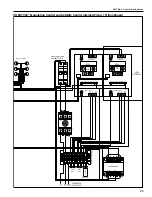
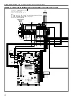
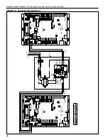
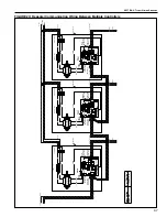
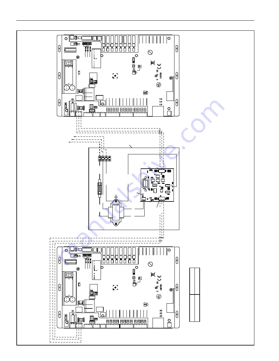
FIGURE 19: Repeater External Wiring
88F0
E143900
TYPE: 002003
Power
Of
f On
Power
Gnd
24V
ac
Port 1
485
ARC-
Shield
Net -
Net +
156
Port 2a
Rnet
Gnd
Rnet +
Rnet -
+12V
Xnet +
Xnet -
Gnd
Xnet Expansion
Local
Rnet+
Gnd
Sense
+12V
Rnet-
Access
EIA-485
EIA-232
Thermistor/
dry-contact/
Mode Select
Universal Input
mA
RT
D
Vo
lt
s
10V Max, 20mA
Max
Inputs: All
UI-4
UI-3
UI-2
UI-1
Gnd
+
Gnd
Gnd
+
+
Gnd
+
8
7
6
5
4
3
2
1
UI-8
Gnd
UI-6
UI-7
UI-5
Gnd
+
+
Gnd
+
Gnd
+
UI-12
UI-1
1
UI-10
UI-9
+
Gnd
+
Gnd
Gnd
+
Gnd
+
24 Vdc
24 Vdc
200mA
maximum
Auto Of
f On
0-20mA
0-10Vdc
Relay
Controller
Address
1's
10's
Archive V
a
lid
Port 2a Rx
Port 2a
Tx
Port 1 Rx
Port 1
Tx
Battery low
Ext. Batt.
Int. Batt.
External
Battery
Gnd
+3V
Status
Module
3V Lithium Battery
CR-123A
0 = Download required
3 = Comm setup error
1 = Control Program Error
4 = System error
8 = Formatting
2 = RAM full
Chase = OK
Status Codes
Class 2
ONL
Y
Use Copper
24V
ac, 50V
A
Without Keypad:
26Vdc, 23W
, 0.9A
Outputs
24Vdc Max, 50mA
Max
Format
Pot
2-wire
4-wire
2 wire
4 wire
Rx -
Net-
Net+
n/c
Tx -
Tx +
Rx +
n/c
EIA-232
DCD
Rx
Tx
DTR
Signal Ground
®
BACnet
Over ARCNET156
KBaud
Made in USA
Port 2a BT485
Port 1
Port 1 BT485
Conductors
2A, 50-60 Hz
Blinking Dot = 'Run'
On
Of
f
Enhanced
8
7
6
5
4
3
2
1
8
7
6
5
4
3
2
1
IP
Addr
Assigned
Default
10/100 BaseT
Ethernet Port E1
100
LAN
L
INK
®
8
7
6
5
See BAS
T
able Below
Protocols
6
MS/TP
m
MS/TP
s
Of
f
N2
On
Lon S
L
T
A
Of
f
BAUD
4
5
9600
Of
f
O
ff
19.2 K
O
ff
On
38.4 K
O
n
O
ff
76.8 K
O
n
O
n
On
Modbus
8
Of
f
Of
f
On
On
Of
f
4
BACnet
3
7
Of
f
On
Of
f
Of
f
Of
f
PTP
O
ff
Of
f
On
Access Port 2a
Lon Option
Of
f
On
On
2
1
UO-1
UO-2
UO-3
UO-4
UO-8
UO-7
UO-6
UO-5
On
Of
f
2
1
BAS Port
BAS Port Settings
Set Pot Full CW
24V
ac
DO NOT
APPL
Y
24V
ac
T
O
UNIVERSAL
OUTPUTS
External 24Vdc relay coil only
Brownout
3
UO-2
UO-1
2
1
UO-4
UO-3
6
5
4
7
8
6
UO-7
UO-6
UO-5
3
1
2
4
5
UO-8
7
8
+
Gnd
+
Gnd
+
Gnd
+
Gnd
+
Gnd
+
Gnd
+
Gnd
+
Gnd
Aux Power Out
Port 2b
Port 2a
IOPro812u
07/10/12
Rev 6
Open Energy
Management Equipment
26Vdc
I/O P
ro 812u
C
O
NTROLLER
88F0
E143900
TYPE: 002003
Power
Of
f On
Power
Gnd
24V
a
c
Port 1
485
ARC-
Shield
Net -
Net +
156
Port 2a
Rnet
Gnd
Rnet +
Rnet -
+12V
Xnet +
Xnet -
Gnd
Xnet Expansion
Local
Rnet+
Gnd
Sense
+12V
Rnet-
Access
EIA-485
EIA-232
Thermistor/
dry-contact/
Mode Select
Universal Input
mA
RT
D
Vo
lt
s
10V Max, 20mA
Max
Inputs: All
UI-4
UI-3
UI-2
UI-1
Gnd
+
Gnd
Gnd
+
+
Gnd
+
8
7
6
5
4
3
2
1
UI-8
Gnd
UI-6
UI-7
UI-5
Gnd
+
+
Gnd
+
Gnd
+
UI-12
UI-1
1
UI-10
UI-9
+
Gnd
+
Gnd
Gnd
+
Gnd
+
24 Vdc
24 Vdc
200mA
maximum
Auto Of
f On
0-20mA
0-10Vdc
Relay
Controller
Address
1's
10's
Archive V
a
lid
Port 2a Rx
Port 2a
Tx
Port 1 Rx
Port 1
Tx
Battery low
Ext. Batt.
Int. Batt.
External
Battery
Gnd
+3V
Status
Module
3V Lithium Battery
CR-123A
0 = Download required
3 = Comm setup error
1 = Control Program Error
4 = System error
8 = Formatting
2 = RAM full
Chase = OK
Status Codes
Class 2
ONL
Y
Use Copper
24V
ac, 50V
A
Without Keypad:
26Vdc, 23W
, 0.9A
Outputs
24Vdc Max, 50mA
Max
Format
Pot
2-wire
4-wire
2 wire
4 wire
Rx -
Net-
Net+
n/c
Tx -
Tx +
Rx +
n/c
EIA-232
DCD
Rx
Tx
DTR
Signal Ground
®
BACnet
Over ARCNET156
KBaud
Made in USA
Port 2a BT485
Port 1
Port 1 BT485
Conductors
2A, 50-60 Hz
Blinking Dot = 'Run'
On
Of
f
Enhanced
8
7
6
5
4
3
2
1
8
7
6
5
4
3
2
1
IP
Addr
Assigned
Default
10/100 BaseT
Ethernet Port E1
100
LAN
L
INK
®
8
7
6
5
See BAS
T
able Below
Protocols
6
MS/TP
m
MS/TP
s
Of
f
N2
On
Lon SL
T
A
Of
f
BAUD
4
5
9600
O
ff
Of
f
19.2 K
O
ff
On
38.4 K
O
n
O
ff
76.8 K
O
n
O
n
On
Modbus
8
Of
f
Of
f
On
On
Of
f
4
BACnet
3
7
Of
f
On
Of
f
Of
f
Of
f
PTP
O
ff
Of
f
On
Access Port 2a
Lon Option
Of
f
On
On
2
1
UO-1
UO-2
UO-3
UO-4
UO-8
UO-7
UO-6
UO-5
On
Of
f
2
1
BAS Port
BAS Port Settings
Set Pot Full CW
24V
ac
DO NOT
APPL
Y
24V
ac
T
O
UNIVERSAL
OUTPUTS
External 24Vdc relay coil only
Brownout
3
UO-2
UO-1
2
1
UO-4
UO-3
6
5
4
7
8
6
UO-7
UO-6
UO-5
3
1
2
4
5
UO-8
7
8
+
Gnd
+
Gnd
+
Gnd
+
Gnd
+
Gnd
+
Gnd
+
Gnd
+
Gnd
Aux Power Out
Port 2b
Port 2a
IOPro812u
07/10/12
Rev 6
Open Energy
Management Equipment
26Vdc
I/O P
ro 812u
C
O
NTROLLER
Net +
Net +
Net
-
Net
-
Shield
Shield
REP 485
ON OFF
B
T
485
C
O
NNEC
T
O
R
ER
TH GROUND
POWER
C
O
NNEC
T
O
R
(NE
T
WORK B)
(NE
T
WORK B)
POWER
JUMPER
C
O
NNEC
T
O
R
B
T
485
C
ONNEC
T
O
R
(NE
T
WORK A
)
C
O
NNEC
T
O
R
(NE
T
WORK A
)
LED1
LED2
24 V
a
c
LINE
LO
A
D
3
1
4
5
Shield
0.8 Amps
. F
u
se
To
Nex
t
C
o
ntr
o
ller
1 2
Shield
2
1
3 2 1
1 2 3
LED3
120V 60HZ
24V 20V
A
TRANSFORMER
Te
rminal Block
BASE PLA
T
E
GREEN
BLA
C
K
BLA
C
K
WHITE
BL
UE
Y
ELL
OW
Fr
om P
revious
C
o
ntr
oller
Net -
Net +
Net-
Net+
120 V
a
c
HO
T
NEUTRAL
GND
GREEN
Descr
iption
P
ar
t Number
R
epeat
er
1
0060
1
5
6
Summary of Contents for CORAYVAC
Page 2: ......
Page 4: ......
Page 69: ...SECTION 8 PROGRAMMING AND TROUBLESHOOTING THE SYSTEM 65 THIS PAGE LEFT INTENTIONALLY BLANK ...
Page 71: ...SECTION 9 TROUBLESHOOTING 67 FIGURE 26 Vacuum pump does not turn on ...
Page 75: ...SECTION 9 TROUBLESHOOTING 71 FIGURE 31 Burner troubleshooting in manual mode ...
Page 77: ...SECTION 9 TROUBLESHOOTING 73 After 45 second prepurge burners do not light continued ...
Page 81: ...SECTION 9 TROUBLESHOOTING 77 FIGURE 36 Air Pressure Switch alarm ...
Page 83: ...SECTION 9 TROUBLESHOOTING 79 FIGURE 38 Repeater troubleshooting ...
Page 85: ...SECTION 9 TROUBLESHOOTING 81 BACnet MS TP troubleshooting continued ...
Page 109: ...SECTION 13 TOUCHSCREEN TREE 105 Touchscreen Tree Overview continued ...
Page 111: ...SECTION 13 TOUCHSCREEN TREE 107 FIGURE 47 Maintenance Unit FIGURE 48 Alarms ...
Page 113: ...SECTION 13 TOUCHSCREEN TREE 109 FIGURE 51 Configuration Zones FIGURE 52 Configuration Unit ...
Page 115: ...SECTION 13 TOUCHSCREEN TREE 111 FIGURE 55 Touchscreen System FIGURE 56 Touchscreen Setup ...
Page 118: ...ROBERTS GORDON CORAYVAC MODULATING HEATING CONTROL CONTROLLER INSTALLATION MANUAL 114 ...

