ROBERTS GORDON
®
CORAYVAC
®
M
ODULATING
H
EATING
C
ONTROL
C
ONTROLLER
I
NSTALLATION
M
ANUAL
42
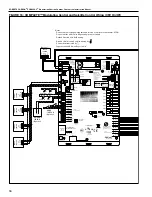
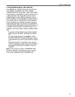
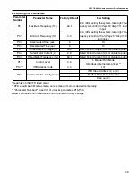
5.7 Control Board Setup
Universal Inputs and Outputs, Ports, Rotary Switches
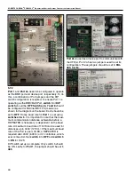
and DIP switches must all be configured for the board
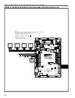
to work properly. Reference the labeled control
board,
, for help locating parts on
the control board.
Jumper setting on I/O Pro controller,
• HOA Switches set to "AUTO"
• Universal Output jumpers for UO-1, UO-2, UO-3,
and UO-4 set to "RELAY"
• Jumpers for UO-5, UO-6, UO7 and UO-8 set to
"0-10v"
• Universal input jumpers for UI-1, UI-2, and UI-3
set to Thermistor/dry-contact/ RTD"
• UI-4 and UI-5 can be optionally used for manual
pump operation
• Port 1 jumpers set to "485"
• Port 2a jumpers configured for "EIA485, 2
WIRES"
• The CORAYVAC
®
On/Off system uses universal
outputs 7 and 8 to control the pumps. In this case,
the jumper for UO's 7 and 8 is set to Relay.
Summary of Contents for CORAYVAC
Page 2: ......
Page 4: ......
Page 69: ...SECTION 8 PROGRAMMING AND TROUBLESHOOTING THE SYSTEM 65 THIS PAGE LEFT INTENTIONALLY BLANK ...
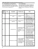
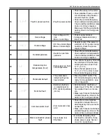
Page 71: ...SECTION 9 TROUBLESHOOTING 67 FIGURE 26 Vacuum pump does not turn on ...
Page 75: ...SECTION 9 TROUBLESHOOTING 71 FIGURE 31 Burner troubleshooting in manual mode ...
Page 77: ...SECTION 9 TROUBLESHOOTING 73 After 45 second prepurge burners do not light continued ...
Page 81: ...SECTION 9 TROUBLESHOOTING 77 FIGURE 36 Air Pressure Switch alarm ...
Page 83: ...SECTION 9 TROUBLESHOOTING 79 FIGURE 38 Repeater troubleshooting ...
Page 85: ...SECTION 9 TROUBLESHOOTING 81 BACnet MS TP troubleshooting continued ...
Page 109: ...SECTION 13 TOUCHSCREEN TREE 105 Touchscreen Tree Overview continued ...
Page 111: ...SECTION 13 TOUCHSCREEN TREE 107 FIGURE 47 Maintenance Unit FIGURE 48 Alarms ...
Page 113: ...SECTION 13 TOUCHSCREEN TREE 109 FIGURE 51 Configuration Zones FIGURE 52 Configuration Unit ...
Page 115: ...SECTION 13 TOUCHSCREEN TREE 111 FIGURE 55 Touchscreen System FIGURE 56 Touchscreen Setup ...
Page 118: ...ROBERTS GORDON CORAYVAC MODULATING HEATING CONTROL CONTROLLER INSTALLATION MANUAL 114 ...

