SECTION 6: V
ARIABLE
F
REQUENCY
D
RIVE
P
ROGRAMMING
49
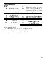
6.2 Altering VFD Parameters
*Depends on the VFD rated power
**VFD should be in Modbus mode, unless manual mode is desired temporarily.
***Parameter Number P14 set to 101 unlocks parameters P15-P53.
Note:
Parameters not listed above should be left at factory settings.
Parameter
Number
Parameter Name
Factory Default
New Setting
P01
Maximum Frequency (Hz)
50.0
60.0 (After setting the system, take right Fre-
quency according to
Page 57, Step 7.1.1
and
input.)
P02
Minimum Frequency (Hz)
0.0
40.0 (After setting the system, take right Fre-
quency according the to
Page 57 Step 7.1.3
and input.)
P03
Accelerated Time (sec)
5
10
P04
Decelerated Time (sec)
5
10
P07
Nominal Motor Voltage (V)
230*
Rated Motor Voltage (from motor data plate)
P08
Rated Motor Current (A)
4.8
Rated Motor Current (from motor data plate)
P09
Rated Motor Frequency (Hz)
50.0
Rated Motor Current (from motor data plate)
P12
Control Level
0.0
1- Manual Run Mode
3-Modbus (internal ramp time) **
P14***
VFD Access Code
0.0
101
P36
Communication Configuration
-
VFD Slave Address (1) or (2)
-
Modbus RTU baud rate (9.6)
-
Time out (0)
Summary of Contents for CORAYVAC
Page 2: ......
Page 4: ......
Page 69: ...SECTION 8 PROGRAMMING AND TROUBLESHOOTING THE SYSTEM 65 THIS PAGE LEFT INTENTIONALLY BLANK ...
Page 71: ...SECTION 9 TROUBLESHOOTING 67 FIGURE 26 Vacuum pump does not turn on ...
Page 75: ...SECTION 9 TROUBLESHOOTING 71 FIGURE 31 Burner troubleshooting in manual mode ...
Page 77: ...SECTION 9 TROUBLESHOOTING 73 After 45 second prepurge burners do not light continued ...
Page 81: ...SECTION 9 TROUBLESHOOTING 77 FIGURE 36 Air Pressure Switch alarm ...
Page 83: ...SECTION 9 TROUBLESHOOTING 79 FIGURE 38 Repeater troubleshooting ...
Page 85: ...SECTION 9 TROUBLESHOOTING 81 BACnet MS TP troubleshooting continued ...
Page 109: ...SECTION 13 TOUCHSCREEN TREE 105 Touchscreen Tree Overview continued ...
Page 111: ...SECTION 13 TOUCHSCREEN TREE 107 FIGURE 47 Maintenance Unit FIGURE 48 Alarms ...
Page 113: ...SECTION 13 TOUCHSCREEN TREE 109 FIGURE 51 Configuration Zones FIGURE 52 Configuration Unit ...
Page 115: ...SECTION 13 TOUCHSCREEN TREE 111 FIGURE 55 Touchscreen System FIGURE 56 Touchscreen Setup ...
Page 118: ...ROBERTS GORDON CORAYVAC MODULATING HEATING CONTROL CONTROLLER INSTALLATION MANUAL 114 ...

