ROBERTS GORDON
®
CORAYVAC
®
M
ODULATING
H
EATING
C
ONTROL
C
ONTROLLER
I
NSTALLATION
M
ANUAL
50
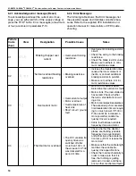
6.2.1 Acknowledge error message (Reset)
To acknowledge and reset the current error mes-
sage, you can either switch off the supply voltage or
press the STOP button. Error messages (a maximum
of four) are stored in parameter P-13.
6.2.2 Error Messages
The following table shows the Error messages list,
the possible causes and indicates corrective mea-
sures. Refer to the supplied VFD installation and
operation manual for more details or VFD trouble-
shooting.
Failure
Code
[hex]
View
Designation
Possible Cause
Notes
01
01-b
Braking chopper over
current
• Overcurrent braking
resistance
• Overcurrent in braking resistor
circuit.
• Check the wiring to the braking
resistance.
• Check the brake resistor value.
Make sure to adhere to mini-
mum resistance values.
02
0L-br
Thermal overload braking
resistance
• Braking resistance
overload
• Increase the deceleration time,
reduce the load's moment of
inertia, or connect additional
braking resistors in parallel.
• Make sure to adhere to mini-
mum resistance values.
03
0-I
Overcurrent motor
• Overcurrent at output
• Motor overload
• Overtemperature at
heat sink
• Short circuit / ground
fault
• Motor with constant speed:
Determine the overload or fault.
• Motor starts: The load stalled or
has seized. Check whether
there is a star/delta motor wir-
ing error.
• Motor accelerates/decelerates:
The excessively short accelera-
tion/deceleration time is requir-
ing too much power. If P-03 or
P-04 cannot be increased, a
more powerful variable fre-
quency drive is required.
• Cable fault between variable
frequency drive and motor.
04
It-trF
Thermal motor overload
• The DC1 variable fre-
quency drive was
switched off after
more than 100% of
the value set in P-08
was delivered for a
period of time
• Check whether the decimal
places are flashing (variable
frequency drive overloaded)
and either raise the accelera-
tion ramp (P-03) or reduce the
motor load.
• Make sure that the cable length
matches the variable fre-
quency drive specifications.
• Check the load mechanically in
order to make sure that it is
free, that nothing is getting
jammed or locked, and there
are no other mechanical faults.
Summary of Contents for CORAYVAC
Page 2: ......
Page 4: ......
Page 69: ...SECTION 8 PROGRAMMING AND TROUBLESHOOTING THE SYSTEM 65 THIS PAGE LEFT INTENTIONALLY BLANK ...
Page 71: ...SECTION 9 TROUBLESHOOTING 67 FIGURE 26 Vacuum pump does not turn on ...
Page 75: ...SECTION 9 TROUBLESHOOTING 71 FIGURE 31 Burner troubleshooting in manual mode ...
Page 77: ...SECTION 9 TROUBLESHOOTING 73 After 45 second prepurge burners do not light continued ...
Page 81: ...SECTION 9 TROUBLESHOOTING 77 FIGURE 36 Air Pressure Switch alarm ...
Page 83: ...SECTION 9 TROUBLESHOOTING 79 FIGURE 38 Repeater troubleshooting ...
Page 85: ...SECTION 9 TROUBLESHOOTING 81 BACnet MS TP troubleshooting continued ...
Page 109: ...SECTION 13 TOUCHSCREEN TREE 105 Touchscreen Tree Overview continued ...
Page 111: ...SECTION 13 TOUCHSCREEN TREE 107 FIGURE 47 Maintenance Unit FIGURE 48 Alarms ...
Page 113: ...SECTION 13 TOUCHSCREEN TREE 109 FIGURE 51 Configuration Zones FIGURE 52 Configuration Unit ...
Page 115: ...SECTION 13 TOUCHSCREEN TREE 111 FIGURE 55 Touchscreen System FIGURE 56 Touchscreen Setup ...
Page 118: ...ROBERTS GORDON CORAYVAC MODULATING HEATING CONTROL CONTROLLER INSTALLATION MANUAL 114 ...

