SECTION 6: V
ARIABLE
F
REQUENCY
D
RIVE
P
ROGRAMMING
51
05
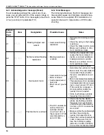
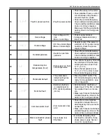
P5-trF
Fault in power section
• Fault in power section
• Check the wiring to the motor.
• Check whether there is a short -
circuit between the phases or
an earth fault in a phase.
• Check the variable frequency
drive's ambient air temperature.
Check whether additional clear-
ance or cooling is required.
Make sure that the variable fre-
quency drive is not being over-
loaded.
06
O.UoI t
Overvoltage
• Overvoltage at DC
link
• Mains overvoltage
• Power supply problem.
• Increase deceleration ramp
time P-04.
07
U.UoI t
Undervoltage
• DC link undervoltage
• Mains Undervoltage
• Usually occurs if the power is
switched off. If it occurs during
operation, check the power
supply voltage.
08
O-t
Overtemperature
• Heat sink overtem-
perature
• Check the variable frequency
drive's ambient air temperature.
Check whether additional clear-
ance or cooling is required.
09
U-t
Excessively low
temperature (frost)
• Excessively low heat
sink temperature
• The variable frequency drive will
be switched off if the ambient
air temperature is lower than
14 °F (-10 °C).
• Raise the temperature over
14 °F (-10 °C) in order to start
the variable frequency drive.
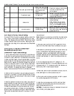
0A
P-dEF
Parameter default
• The parameter's
default setting has
been loaded
• Press the STOP button. The
DC! Variable frequency drive is
ready for an application - spe-
cific configuration.
0B
E-triP
External fault
• External shutdown
(on digital input 3).
• PTC overtemperature
(motor)
• External safety shutdown at
digital input 3. The N/C contact
has opened due to some rea-
son.
• Make sure that each individual
variable frequency drive on the
network has a unique address.
0C
SC-trF
Communication fault
• Communication loss
error
• Check the communications
connection between the vari-
able frequency drive and exter-
nal devices.
• Make sure that each individual
variable frequency drive on the
network has a unique address.
0E
P-Lo55
Mains connection phase
fault
• Input phase loss
• Shutdown
• A variable frequency drive
intended for use with a three-
phase power supply has lost
one of its input phases.
Summary of Contents for CORAYVAC
Page 2: ......
Page 4: ......
Page 69: ...SECTION 8 PROGRAMMING AND TROUBLESHOOTING THE SYSTEM 65 THIS PAGE LEFT INTENTIONALLY BLANK ...
Page 71: ...SECTION 9 TROUBLESHOOTING 67 FIGURE 26 Vacuum pump does not turn on ...
Page 75: ...SECTION 9 TROUBLESHOOTING 71 FIGURE 31 Burner troubleshooting in manual mode ...
Page 77: ...SECTION 9 TROUBLESHOOTING 73 After 45 second prepurge burners do not light continued ...
Page 81: ...SECTION 9 TROUBLESHOOTING 77 FIGURE 36 Air Pressure Switch alarm ...
Page 83: ...SECTION 9 TROUBLESHOOTING 79 FIGURE 38 Repeater troubleshooting ...
Page 85: ...SECTION 9 TROUBLESHOOTING 81 BACnet MS TP troubleshooting continued ...
Page 109: ...SECTION 13 TOUCHSCREEN TREE 105 Touchscreen Tree Overview continued ...
Page 111: ...SECTION 13 TOUCHSCREEN TREE 107 FIGURE 47 Maintenance Unit FIGURE 48 Alarms ...
Page 113: ...SECTION 13 TOUCHSCREEN TREE 109 FIGURE 51 Configuration Zones FIGURE 52 Configuration Unit ...
Page 115: ...SECTION 13 TOUCHSCREEN TREE 111 FIGURE 55 Touchscreen System FIGURE 56 Touchscreen Setup ...
Page 118: ...ROBERTS GORDON CORAYVAC MODULATING HEATING CONTROL CONTROLLER INSTALLATION MANUAL 114 ...

