ROBERTS GORDON
®
CORAYVAC
®
M
ODULATING
H
EATING
C
ONTROL
C
ONTROLLER
I
NSTALLATION
M
ANUAL
90
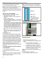
4. Port 1 on the I/O Pro 812u control board is the only
port that supports BACnet over ARC 156. Connect
BACnet over ARC 156 communications wiring to Port
1 in the screw terminals labeled Net +,
Net - and Gnd. Set Port 1 Mode jumper to ARC
156.
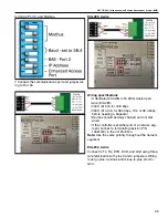
Wiring Specifications
The I/O Pro 812u (control board) network can consist
of multiple network segments. Each segment of an I/
O Pro 812u network must:
• Be wired in a daisy-chain configuration
• Be no longer than 2000’ (610 m)
• Have 32 or fewer devices (controllers and repeat-
ers)
It is required to have one of the following:
• A repeater (P/N 10060156) at each end (unless
the segment is less than 10’ [3 m] long) to add
bias and prevent signal distortions due to echo-
ing.
• A 1/2 watt, 120 Ohm resistor at each end to pre-
vent signal distortions due to echoing and one
DIAG485 near the center of the network segment
to add bias. You must put the DIAG485’s
Bias
jumper in place.
5. Turn on power to control board.
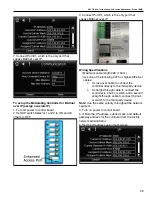
6. Set the correct network number to the unique
BACnet ARC156 network at the site.
7. Set a unique Device Instance number.
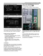
The most common communication problems result
from not properly following the configuration steps
outlined above. Review all steps and use the
following list to check your settings. Verify accuracy
of the following:
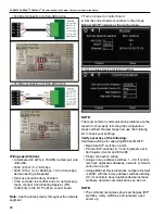
Hardware settings
• ARC156 protocol DIP switches 6, 7, and 8 off.
• Proper connection wiring.
•
Unique rotary address switches 1 – 99. If control-
lers
have duplicate addresses, network communi-
cation can be lost.
•
Unique BACnet Device Instance numbers.
Default is
24XX, with the rotary address switches
defining XX. If controllers have duplicate device
instance numbers, network communication can
be lost.
•
The controller recognizes physical changes (DIP
switches,
rotary switches, and jumpers) upon
power up.
• If RX LED is solid, then the terminations are incor-
rect.
•
If the network has greater than 32 devices or
exceeds
2000’ (610 m) a Repeater should be
installed.
•
If a controller begins or ends a network segment,
a
terminating resistor (P/N 10061018) may be
needed.
Summary of Contents for CORAYVAC
Page 2: ......
Page 4: ......
Page 69: ...SECTION 8 PROGRAMMING AND TROUBLESHOOTING THE SYSTEM 65 THIS PAGE LEFT INTENTIONALLY BLANK ...
Page 71: ...SECTION 9 TROUBLESHOOTING 67 FIGURE 26 Vacuum pump does not turn on ...
Page 75: ...SECTION 9 TROUBLESHOOTING 71 FIGURE 31 Burner troubleshooting in manual mode ...
Page 77: ...SECTION 9 TROUBLESHOOTING 73 After 45 second prepurge burners do not light continued ...
Page 81: ...SECTION 9 TROUBLESHOOTING 77 FIGURE 36 Air Pressure Switch alarm ...
Page 83: ...SECTION 9 TROUBLESHOOTING 79 FIGURE 38 Repeater troubleshooting ...
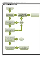
Page 85: ...SECTION 9 TROUBLESHOOTING 81 BACnet MS TP troubleshooting continued ...
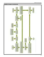
Page 109: ...SECTION 13 TOUCHSCREEN TREE 105 Touchscreen Tree Overview continued ...
Page 111: ...SECTION 13 TOUCHSCREEN TREE 107 FIGURE 47 Maintenance Unit FIGURE 48 Alarms ...
Page 113: ...SECTION 13 TOUCHSCREEN TREE 109 FIGURE 51 Configuration Zones FIGURE 52 Configuration Unit ...
Page 115: ...SECTION 13 TOUCHSCREEN TREE 111 FIGURE 55 Touchscreen System FIGURE 56 Touchscreen Setup ...
Page 118: ...ROBERTS GORDON CORAYVAC MODULATING HEATING CONTROL CONTROLLER INSTALLATION MANUAL 114 ...


