ROBERTS GORDON
®
CORAYVAC
®
M
ODULATING
H
EATING
C
ONTROL
C
ONTROLLER
I
NSTALLATION
M
ANUAL
48
SECTION 6: VARIABLE FREQUENCY DRIVE PROGRAMMING
6.1 VFD Parameter Settings For Use With
ROBERTS GORDON
®
CORAYVAC
®
Modulating
Heating Control
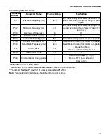
The VFD parameters come with factory default set-
tings. The following parameter settings must be
changed. Settings can only be altered when the
pump motor is stopped.
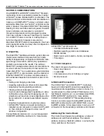
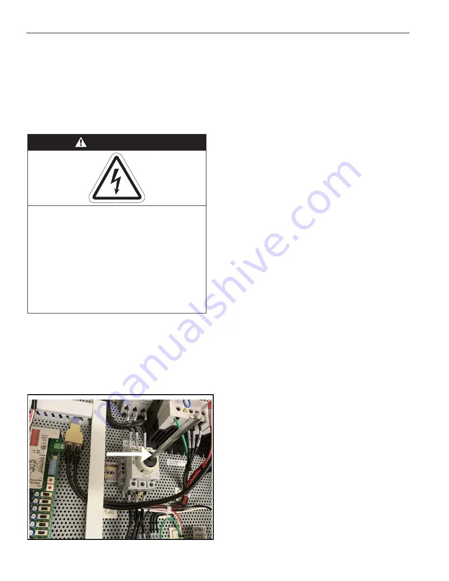
To override the VFD parameters, turn the square rod
of the rotary disconnect switch inside the Controller
enclosure with a wrench clockwise to the ON posi-
tion. In order to be able to close the cover of the dis-
connect, the rod needs to be turned back to the OFF
position.
FIGURE 23: VFD Override
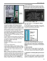
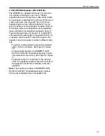
6.1.1 Program Mode
To enter the PROGRAM mode and access the
Parameters, hold "OK" until P01 appears. Display
reads "P01".
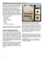
6.1.2 Unlock Parameter Higher than P14
Use the arrow buttons to scroll to P14 (the factory set
password is 0.0). Press "OK" to enter password
(101). This unlocks parameters higher than P14.
6.1.3 Scroll Up or Down
Use the arrow buttons to scroll to the desired param-
eter number. For new parameter settings,
.
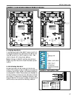
6.1.4 Change a Parameter
Once the desired parameter number is found: Press
"OK" to display present parameter setting (example
setting is 20.0). Use arrow buttons to change setting.
Press "OK" to store new setting. Continue scrolling
through the parameters.
DANGER
Electrical Shock Hazard
Enclosure contains live electrical
components.
Programming must be done by a trained
technician only.
Replace cover before operating.
Failure to follow these instructions can result
in death or electrical shock.
Summary of Contents for CORAYVAC
Page 2: ......
Page 4: ......
Page 69: ...SECTION 8 PROGRAMMING AND TROUBLESHOOTING THE SYSTEM 65 THIS PAGE LEFT INTENTIONALLY BLANK ...
Page 71: ...SECTION 9 TROUBLESHOOTING 67 FIGURE 26 Vacuum pump does not turn on ...
Page 75: ...SECTION 9 TROUBLESHOOTING 71 FIGURE 31 Burner troubleshooting in manual mode ...
Page 77: ...SECTION 9 TROUBLESHOOTING 73 After 45 second prepurge burners do not light continued ...
Page 81: ...SECTION 9 TROUBLESHOOTING 77 FIGURE 36 Air Pressure Switch alarm ...
Page 83: ...SECTION 9 TROUBLESHOOTING 79 FIGURE 38 Repeater troubleshooting ...
Page 85: ...SECTION 9 TROUBLESHOOTING 81 BACnet MS TP troubleshooting continued ...
Page 109: ...SECTION 13 TOUCHSCREEN TREE 105 Touchscreen Tree Overview continued ...
Page 111: ...SECTION 13 TOUCHSCREEN TREE 107 FIGURE 47 Maintenance Unit FIGURE 48 Alarms ...
Page 113: ...SECTION 13 TOUCHSCREEN TREE 109 FIGURE 51 Configuration Zones FIGURE 52 Configuration Unit ...
Page 115: ...SECTION 13 TOUCHSCREEN TREE 111 FIGURE 55 Touchscreen System FIGURE 56 Touchscreen Setup ...
Page 118: ...ROBERTS GORDON CORAYVAC MODULATING HEATING CONTROL CONTROLLER INSTALLATION MANUAL 114 ...

