ROBERTS GORDON
®
CORAYVAC
®
M
ODULATING
H
EATING
C
ONTROL
C
ONTROLLER
I
NSTALLATION
M
ANUAL
2
1.6 General Requirements
The ROBERTS GORDON
®
CORAYVAC
®
Modulating
Heating Control series of controllers are supplied pre-
configured for use with ROBERTS GORDON
®
CORAYVAC
®
infrared heating equipment only. Fail-
ure to comply with the installation instructions and
configuration may invalidate the ROBERTS GOR-
DON
®
CORAYVAC
®
Modulating Heating Control lim-
ited warranty.
The controller, variable frequency drive, burners,
pump and outside air blower must be electrically
grounded in accordance with the National Electrical
Code
®
ANSI/NFPA 70 - latest revision.
Before proceeding with the installation of the control-
ler, it will be necessary to check that the following
points have been considered:
1.7 CORAYVAC
®
Design Requirements
(Modulating Systems)
CORAYVAC
®
burners shall be CRV B-6, B-8, B-9,
B-10 or B-12 burners.
CORAYVAC
®
systems designed shall have
minimum
radiant pipe length and 1.5 - 2.0’ per flow
unit of tailpipe length.
-OR-
CORAYVAC
®
systems designed shall have
recommended
radiant pipe length and 1.2 - 1.5’ per
flow unit of tailpipe length. See the CORAYVAC
®
Design Manual (P/N 127500NA) for minimum and
recommended radiant pipe length.
1.8 CORAYVAC
®
Design Requirements (On/Off
Systems)
CORAYVAC
®
burners shall be CRV B-2, B-4, B-6, B-
8, B-9, B-10, B-12A, or B-12 burners.
Radiant and tail pipe lengths shall comply with
design requirements specified in CORAYVAC
®
Design Manual (P/N 127500NA).
and
for
on/off system specific setup.
Note: Use COMPLETE™ Modulating Heating Con-
trol (P/N 10060042 or 10060142) for these installa-
tions.
1.9 VANTAGE
®
CTHN Multiburner Systems
Burners shall be VANTAGE
®
CTHN.
Radiant and manifold pipe lengths shall comply with
design requirements specified in VANTAGE
®
CTHN
Installation, Operation, and Service Manual (P/N
152101NA).
Note: Use COMPLETE™ Modulating Heating Con-
trol (P/N 10060042 or 10060142) for these installa-
tions.
1.10 Unitary Design Requirements
Burners shall be VANTAGE
®
CTH3, HEM, CTH2V,
HEV, TF, CTHN or GORDONRAY
®
BH. Only VAN-
TAGE
®
CTH3/HEM burners will modulate. All other
burners will operate as on/off.
Note: GORDONRAY
®
DF (two-stage unitary heater)
will not function with CORAYVAC
®
or COMPLETE™
Modulating Heating Control.
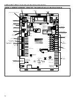
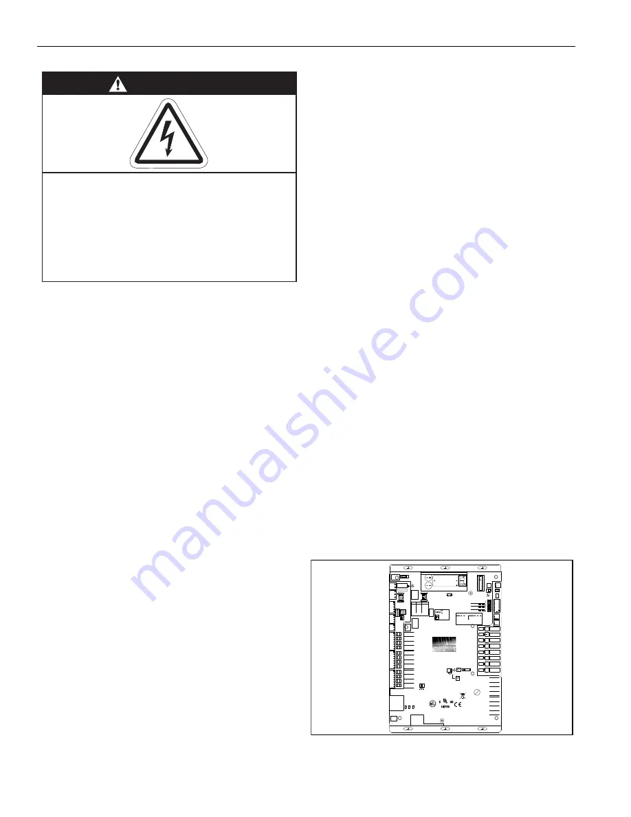
1.11 Control Board and Sensor Power
The power supply for all sensors is from the “+12 V”
terminal on the Rnet port of control board. Power for
the control board is 24 V provided by the transformer.
DANGER
Electrical Shock Hazard
Disconnect electric before service.
Controller must be properly grounded to an
electrical source.
Failure to follow these instructions can
result in death or electrical shock.
88F0
E143900
TYPE: 002003
Power
Off On
Power
Gnd
24Vac
Port 1
485
ARC-
Shield
Net -
Net +
156
Port 2a
Rnet
Gnd
Rnet +
Rnet -
+12V
Xnet +
Xnet -
Gnd
Xnet Expansion
Local
Rnet+
Gnd
Sense
+12V
Rnet-
Access
EIA-485
EIA-232
Thermistor/
dry-contact/
Mode Select
Universal Input
mA
RTD
Volts
10V Max, 20mA Max
Inputs: All
UI-4
UI-3
UI-2
UI-1
Gnd
+
Gnd
Gnd
+
+
Gnd
+
8
7
6
5
4
3
2
1
UI-8
Gnd
UI-6
UI-7
UI-5
Gnd
+
+
Gnd
+
Gnd
+
UI-12
UI-11
UI-10
UI-9
+
Gnd
+
Gnd
Gnd
+
Gnd
+
24 Vdc
24 Vdc
200mA maximum
Auto Off On
0-20mA
0-10Vdc
Relay
Controller
Address
1's
10's
Archive Valid
Port 2a Rx
Port 2a Tx
Port 1 Rx
Port 1 Tx
Battery low
Ext. Batt.
Int. Batt.
External
Battery
Gnd
+3V
Status
Module
3V Lithium Battery
CR-123A
0 = Download required
3 = Comm setup error
1 = Control Program Error
4 = System error
8 = Formatting
2 = RAM full
Chase = OK
Status Codes
Class 2
ONLY Use Copper
24Vac, 50VA
Without Keypad:
26Vdc, 23W, 0.9A
Outputs
24Vdc Max, 50mA Max
Format
Pot
2-wire
4-wire
2 wire4 wire
Rx -
Net-
Net+
n/c
Tx -
Tx +
Rx +
n/c
EIA-232
DCD
Rx
Tx
DTR
Signal Ground
®
BACnet
Over ARCNET156 KBaud
Made in USA
Port 2a BT485
Port 1
Port 1 BT485
Conductors
2A, 50-60 Hz
Blinking Dot = 'Run'
On
Off
Enhanced
8
7
6
5
4
3
2
1
8
7
6
5
4
3
2
1
IP Addr
Assigned Default
10/100 BaseT
Ethernet Port E1
100
LAN
LINK
®
8
7
6
5
See BAS Table Below
Protocols 6
MS/TP m
MS/TP s
Off
N2
On
Lon SLTA
Off
BAUD 4
5
9600 Off
Off
19.2 K Off
On
38.4 K On Off
76.8 K On
On
On
Modbus
8
Off
Off
On
On
Off
4
BACnet
3
7
Off
On
Off
Off
Off
PTP
Off
Off
On
Access Port 2a
Lon OptionOff
On
On
2
1
UO-1
UO-2
UO-3
UO-4
UO-8
UO-7
UO-6
UO-5
On
Off
2
1
BAS Port
BAS Port Settings
Set Pot Full CW
24Vac
DO NOT APPLY 24Vac TO
UNIVERSAL OUTPUTS
External 24Vdc relay coil only
Brownout
3
UO-2
UO-1
2
1
UO-4
UO-3
6
5
4
7
8
6
UO-7
UO-6
UO-5
3
1
2
4
5
UO-8
7
8
+
Gnd
+
Gnd
+
Gnd
+
Gnd
+
Gnd
+
Gnd
+
Gnd
+
Gnd
Aux Power Out
Port 2b
Port 2a
IOPro812u
07/10/12
Rev 6
Open Energy
Management Equipment
26Vdc
Summary of Contents for CORAYVAC
Page 2: ......
Page 4: ......
Page 69: ...SECTION 8 PROGRAMMING AND TROUBLESHOOTING THE SYSTEM 65 THIS PAGE LEFT INTENTIONALLY BLANK ...
Page 71: ...SECTION 9 TROUBLESHOOTING 67 FIGURE 26 Vacuum pump does not turn on ...
Page 75: ...SECTION 9 TROUBLESHOOTING 71 FIGURE 31 Burner troubleshooting in manual mode ...
Page 77: ...SECTION 9 TROUBLESHOOTING 73 After 45 second prepurge burners do not light continued ...
Page 81: ...SECTION 9 TROUBLESHOOTING 77 FIGURE 36 Air Pressure Switch alarm ...
Page 83: ...SECTION 9 TROUBLESHOOTING 79 FIGURE 38 Repeater troubleshooting ...
Page 85: ...SECTION 9 TROUBLESHOOTING 81 BACnet MS TP troubleshooting continued ...
Page 109: ...SECTION 13 TOUCHSCREEN TREE 105 Touchscreen Tree Overview continued ...
Page 111: ...SECTION 13 TOUCHSCREEN TREE 107 FIGURE 47 Maintenance Unit FIGURE 48 Alarms ...
Page 113: ...SECTION 13 TOUCHSCREEN TREE 109 FIGURE 51 Configuration Zones FIGURE 52 Configuration Unit ...
Page 115: ...SECTION 13 TOUCHSCREEN TREE 111 FIGURE 55 Touchscreen System FIGURE 56 Touchscreen Setup ...
Page 118: ...ROBERTS GORDON CORAYVAC MODULATING HEATING CONTROL CONTROLLER INSTALLATION MANUAL 114 ...


