background image

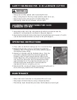
WARNING

• Always wear safety glasses when operating this tool

• Keep cutting blade in the fully closed position when not in use

• Keep fingers and hands away from blade cutting area

• Periodically check that all hardware remains tight

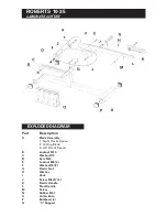
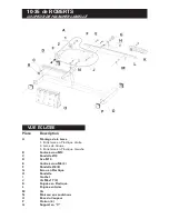
1. Assemble handle (G) to the cutting blade (2) with the provided screws (H),

washers (F) and locknuts (E) as shown in the parts diagram.

2. Assemble the blade (2) to the cutter base (I) using the two nylon spacers (1 and 3)

and double threaded shaft (D) as shown in the parts diagram.

1. Place cutter on the floor making sure it is on a level surface.

2. Mark the work piece to be cut and insert it against the

backstop. The “V”-Support (L) should be used to support
the laminate while cutting.

3. Always cut laminate with the finished side up. Place the

grooved or indented side of the laminate against the
backstop. (The "tongue" side should be closest to the
blade.) Begin the cut by holding the laminate firmly with
one hand and cutting into the laminate with the blade
approximately 1/2 in. You now have started your cut.
Proceed using both hands with a smooth powerful
downward motion to complete your cut.

4. Remember the cut side will always be placed along the wall to

be covered up by baseboard or finish molding.

• Keep cutter clean and store in a dry place when not in use

• Keep edges of blade sharp by using a sharpening stone

• Periodically check all assembly to ensure that hardware remains tight

SAFETY WARNINGS FOR 10-35 LAMINATE CUTTER

OPERATING INSTRUCTIONS

MAINTENANCE

ASSEMBLY INSTRUCTIONS FOR 10-35
LAMINATE CUTTER

Summary of Contents for 10-35

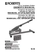
Page 1: ...DE OPERACI N 10 35 WARNING Read and understand all instructions SAVE THESE INSTRUCTIONS FOR FUTURE REFERENCE AVERTISSEMENT Lire et comprendre toutes les directives VEUILLEZ CONSERVER CES DIRECTIVES PO...

Page 2: ...upport the laminate while cutting 3 Always cut laminate with the finished side up Place the grooved or indented side of the laminate against the backstop The tongue side should be closest to the blade...

Page 3: ...Assembly 1 Right Plastic Spacer 2 Cutting Blade 3 Left Plastic Spacer B Locknut M10 C Washer 10 D Axis M10 E Locknut M6 4 F Washer 6 8 G Plastic Nut H Washer I Hook J Screw M6x17 3 K Plastic Handle L...

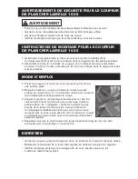
Page 4: ...DE SECURITE POUR LE COUPEUR DE PLANCHER LAMELLE 10 35 MODE D EMPLOI ENTRETIEN INSTRUCTIONS DE MONTAGE POUR LE COUPEUR DE PLANCHER LAMELLE 10 35 Gardez le coupeur propre et rangez le dans un endroit s...

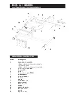
Page 5: ...ite 2 Lame de Coupe 3 Entretoise en Plastique Gauche B Contre crou M10 C Rondelle 10 D Axe M10 E Contre crou M6 4 F Rondelle 6 8 G crou en Plastique H Rondelle I Crochet J Vis M6x17 3 K Poign e en Pla...

Page 6: ...SEGURIDAD PARA EL CORTADOR DE PISOS LAMINADOS 10 35 INSTRUCCIONES DE OPERACI N MANTENIMIENTO INSTRUCCIONES PARA HACER EL ENSAMBLAJE DEL CORTADOR DE PISOS LAMINADOS 10 35 Mantenga el cortador limpio y...

Page 7: ...lla de corte 3 Espaciador de pl stico para la izquierda B Tuerca para bloqueo M10 C Arandela 10 D Eje M10 E Tuerca para bloqueo M6 4 F Arandela 6 8 G Tuerca de pl stico H Arandela I Gancho J Tornillo...

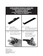
Page 8: ...ARQUE ROBERTS OTROS PRODUCTOS DISPONIBLES DE LA MARCA ROBERTS 10 17 Tapping Block Bloc de taraudage Bloque para dar golpes 10 26 Flooring Installation Kit Kit pour installer le plancher Juego para ins...

Reviews: