background image

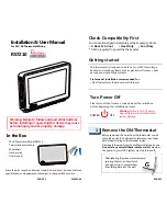
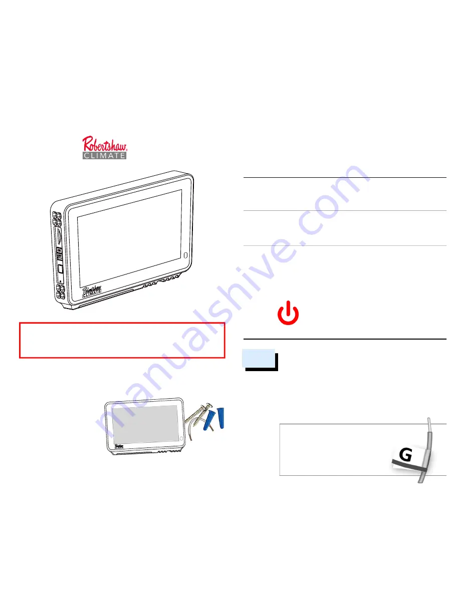
- Wi-Fi Thermostat Model RS7210 
- Two screws and anchors
- Wire labels
- Jumper wire
- User manual 

In the Box

For 24V-AC Thermostat Wiring

Installation & User Manual

RS7210

Before removing the wires from the thermostat or wall 

plate, take a photo of all wires for reference, then label 

each wire according to the terminal codes.  
Disconnect the wires from the old thermostat one by one.  

Do not let any wires fall back into the wall.

 Remember, 

the power to your HVAC system must be turned off. 

After labeling the wires, we recommend 
securing them to an object such 
as a pen or clip to prevent them 
from falling back into the wall.

Remove the Old Thermostat

 1

Please turn off the furnace

s main power at the switchbox 

before beginning the installation process.

POWER               OFF

Warning: 

Failure to turn off power 

may result in electrical shock and/or 

system damage.

Turn Power Off

This thermostat is designed to work on most 24V low voltage 

heating and cooling systems such as gas and oil furnaces, heat 

pumps, and single-stage systems

Professional installation recommended for: 

• Dual fuel systems (heat pump with furnace) 

Getting started

For conventional (gas/oil/electric) and heat-pump systems

> 2-Heat & 1-Cool        > Heat Only      > Cool Only

*


C-Wire required to power the thermostat

Check Compatibility First

Warning: Failure to follow and read all instructions 

before installing or operating this device may cause 

personal injury and/or property damage.

PAGE 01

PAGE 02

250064-00

Some features require an internet connection and a user account. Features, 

specifications, and appearance are subject to change without notice.

Summary of Contents for RS7210

Page 1: ...e switchbox before beginning the installation process POWER OFF Warning Failure to turn off power may result in electrical shock and or system damage Turn Power Off This thermostat is designed to work...

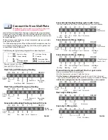
Page 2: ...Y C OB W2 24V Fan Compressor Common Reversing Valve Factory Installed Jumper Conventional Heating Cooling system with C wire RC RH G W Y C OB W2 24V Fan Heat Cool Common Single Transformer Factory Ins...

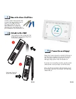
Page 3: ...ck on for the heating cooling system at the main switch box Power On and Enjoy 5 clips 1 push 2 Firmly press forward to secure it into position First align the two clips on the back of the thermostat...

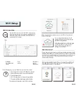
Page 4: ...nked to a user account the date and time on the device will automatically update to the current time associated with the user account APP or WEBPAGE The date and time for the device as well as the use...

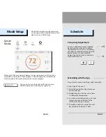
Page 5: ...e device has not been registered by any user will be shown You can now add the device to a user account after downloading the App and setting up an account 4 Wi Fi Setup Off Cool Heat Auto Tap the Mod...

Page 6: ...ailable Wi Fi Networks SSID Cap Letters Numeric or Special Characters Wi Fi can be manually turned off or on Turning off your Wi Fi will also disable the internet connection and all smart features inc...

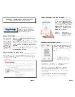
Page 7: ...xciting smart features The MAC ID is a unique network ID for this device this helps to identify your device over the internet The Temporary Verification Code TVC is a 4 digit code that is randomly gen...

Page 8: ...week 2 Scroll left and right to the column you want to change 3 Simply drag the color bar up or down to change the temperature 4 To create a new setpoint tap on a time column then move the rest of th...

Page 9: ...ic or List View SET Set up specific setpoints temperature and time COPY Copy the setpoints to other days of the week System Menu Schedules Schedule on the Thermostat Schedule List There are only two d...

Page 10: ...g setpoints while the system is off Messages will be sent to your account and can be viewed on the device App and Webpage Alerts are informational only Do not use for Life Safety Temperature Alerts an...

Page 11: ...n System Message System generated notices and alerts Screen Timeout Set timeout length for screen auto off during inactivity System Update Manually update system software Verification Code Display a 4...

Page 12: ...oduct has been installed near sources of electromagnetic interference EMI such as arcing relay contacts Owner s Responsibility Provide proof of purchase Provide proof of proof of professional installa...

Reviews: