RC
-
Power Cooling
RH
-
Power Heating
G
-
Fan
W
-
1st Stage Heating
Emergency heat
Y
-
1st Stage Cooling
C
-
Common
O/B
-
Reversing Valve
W2
-
2nd Stage Heating
(
)
........
........
......
Remove jumper wire if you
have both RC & RH wires
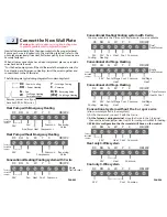
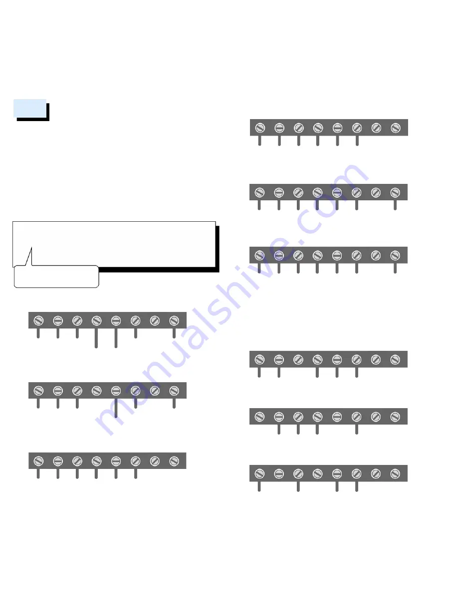
The following are typical wiring diagrams for common systems:
Insert all wires vertically from the open socket into the proper terminal.
Ensure each wire is inserted into the matching terminal (refer to the
photo taken previously if needed).
Pull wires gently to ensure wires are
securely fastened.
When all wire connections have been completed, place any surplus
wires back inside the wall.
*For the heat pump system, if the old thermostat has separate wires for
Aux-Heating and Emergency-Heating, twist the wires together and
connect them to the W terminal.
Warning:
Use caution when securing and routing wires
to prevent possible short to adjacent terminals.
Connect the New Wall Plate
2
Heat Pump with Emergency Heating
RC RH
G
W
Y
C
OB/W2
........
24V
Fan
Compressor
Aux/Emer Heat
Common
Reversing
Valve
Factory
Installed
Jumper
Heat Pump without Emergency Heating
RC RH
G
W
Y
C
OB/W2
........
24V
Fan
Compressor
Common
Reversing
Valve
Factory
Installed
Jumper
Conventional Heating/Cooling system with C wire
RC RH
G
W
Y
C
OB/W2
........
24V
Fan Heat Cool Common
Single
Transformer
Factory
Installed
Jumper
Conventional Heating/Cooling system with C wire
RC RH
G
W
Y
C
OB/W2
24V
Cooling
24V
Heating
Fan Heat Cool Common
Dual
Transformer
You may substitute the C wire with a spare wire if one is available.
Conventional 2nd Stage Heating
RC RH
G
W
Y
C
OB/W2
........
24V Fan
Common
Cool
2nd Stage
Heat
1st Stage
Heat
Single
Transformer
Factory
Installed
Jumper
Conventional 2nd Stage Heating
RC RH
G
W
Y
C
OB/W2
24V
Heating
24V
Cooling
Fan
Common
2 Transformers
Heat & Cool
Cool
2nd Stage
Heat
1st Stage
Heat
1) At the thermostat, connect C with the G wire;
2)
At the furnace
’
s wiring terminal
, move the G wire to the C terminal,
then use the included jumper wire, G with Y for cooling or G with W for heating.
3)
With this configuration the thermostat will have no fan control.
Conventional system without the C or spare wire
(also commonly called a 4-wire system)
RC RH
G
W
Y
C
OB/W2
........
24V
Common
Heat Cool
Factory
Installed
Jumper
Heat only 3-Wire system
RC RH
G
W
Y
C
OB/W2
........
24V
Common
Heat
Cool only 3-Wire system
RC RH
G
W
Y
C
OB/W2
................
24V
Common
Cool
PAGE 03
PAGE 04

