background image

Summary of Contents for EH30V

Page 1: ......

Page 2: ...5 EH17 EH21 EH25 EH30 EH3OV EH34 EH34V EH43V EC13V DY23 DY27 DY30 DY35 DY41 WISCONSIN ROBIN SIDE VALVE w1 080 W1 145 w1 145v W1 185 Wl 185V W1 230 W1 280 W1 340 W1 390 w1 450v EY21W EY44W EY25W EY27W...

Page 3: ...tion System 4 12 Carburetor 4 13 Air Cleaner 4 14 Balancers 4 15 Decompression System 1 2 2 2 2 4 4 4 4 5 5 5 6 6 6 7 7 8 8 8 9 9 4 16 Sectional View Of Engine 10 12 12 12 13 28 42 42 42 43 5 DISASSEM...

Page 4: ......

Page 5: ...1 1 1 3600 HP rpm 8 2 3600 KW rpm 2 41 2500 kg m rpm 17 4 2500 ft lbs rpm 89x69 m m 3 50 X 2 71 in 429 cc 26 1 8 cu in 1 13 3600 HP rpm 9 7 3600 KW rpm 2 85 2500 kg m rpn 20 6 2500 ft Ibs rpm Counterc...

Page 6: ...reak in period when allthemoving parts are properlywornin Therefore a new enginemaynotproducethe maximum outputinthebeginning because the moving partsare notin a properlyworn in condition 2 2 MAXIMUM...

Page 7: ...9 a g 8 a W cn a 0 I 7 6 0 EH43V 13 a I It l 2 1 1 10 9 8 n I MAXIMUM TORQUE I 1 0 2000 2500 3000 3500 4000 L REVOLUTION I P m 2 5 kg m 2 4 2 2 2 1 w 3 8 P L 1500 2 MAXIMUM TORQUE 0 2500 3000 3500 REV...

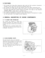
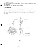
Page 8: ...atorare located on oppositesides makingthearrangementsforcooling air flowmuch easierinthedesign of power equipment 4 GENERAL DESCRIPTION OF ENGINE COMPONENTS 4 1 CYLINDER AND CRANKCASE The cylinder an...

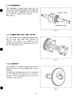
Page 9: ...Theconnectingrodisforgedaluminumalloy and its large and small ends function as bearings The piston is an aluminum alloy casting andcarriestwocompressionrings and one oil ring See Fig 4 Fig 4 4 5 CAMS...

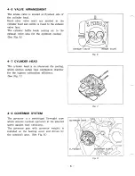
Page 10: ...ling See Fig 6 EXHAUST VALVE INTAKE VALVE Fig 6 4 7 CYLINDER HEAD Thecylinder head is analuminumdiecasting whichutilizes wedge typecombustionchamber forthehighestcombustion efficiency See Fig 7 4 8 GO...

Page 11: ...0V EH34V and EH43V haveatrochoidpumpinsidethemainbearing cover thatis driven by thecamshaft EH3OV and EH34V use forced splash type lubrication while the larger EH43V employs a pressurized lubrication...

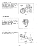
Page 12: ...ig 10 4 12 CARBURETOR The engines are equipped with a horizontal draftcarburetorthat has a floatcontrolled fuel systemandafixedmain jet Thecarburetorsarecalibratedcarefully for the sure starting good...

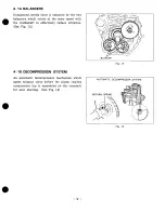
Page 13: ...crankshafttoeffectivelyreducevibration See Fig 13 I BLANCER 4 15 DECOMPRESSION SYSTEM An automatic decompression mechanism which opensexhaustvalvebeforethepistonreaches compression top is assembled on...

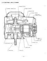
Page 14: ...4 16 SECTIONAL VIEW OF ENGINE rFLYWHEEL COOLING FAN rSTARTINGPULLEY I RECOIL STARTER lo...

Page 15: ...BALANCER SHAFT 2 BALANCER SHAFT 1 CONNECTING ROD TMUFFLER CAP M CARBURETOR AIR CLEANER OIL FILTER CAMSHAFT 1 1...

Page 16: ...hem 2 Have boxes readytokeep disassembed partsbygroup 3 To preventmissingandmisplacing temporarilyassembleeachgroup of disassembedparts 4 Carefullyhandledisassembed parts and clean themwith washing oi...

Page 17: ...s Remove oil drain plug and drain oil 17mm Box wrench Be careful not to lose the gasket Fuel tank 1 Turn off fuel shut off valve and 2 Fuel shut off valve and fuel line lOmm Box wrench remove fuel tan...

Page 18: ...6 d X 2Omm Bolt lpce 6d x l O m m Bolt e lpce base and crankcase cleaner from stud bolts 6 Nut 2pcs 2 Remove air cleaner bracket 3 Remove breather hose from cleaner 4 Remove cleaner base and gasket Ai...

Page 19: ...kerodfrom choke shaft of the carburetor Remarks Memorize or mark the govenor spring hooking position 1 Governor 1 Remove governor lever from governor lever shaft 6 q5 x 25mmBolt a lpce 2 Remove rod sp...

Page 20: ...from stud bolts 2 Remove gasket Insulator and insulator from stud bolts Muffler 1 Remove muffler and muffler cover from stud bolts 8 4 x 16mm Bolt lpce bolts 8 4 Nut 2pcs 2 Remove gasket Muffler from...

Page 21: ...1pce 2 Remove electric starter from crank case 8 9x 30mm Bolt 2pcs 1 Disconnectwires GreedWhite 2 White 1 fromcrank case SeeFig 22 6 q5 x 15mmBolt 2pcs 2 Remove diode rectifier and bracket Remarks Re...

Page 22: ...arks Tool lo I Remove recoil from blower housing 6 x 8mm Bolt e 4pcs I l o r n Box wrench 11 l0mm Box wrench Removeblowerhousing from crankcace Blower housing 6 d X 8 r n Bolt 4pcs 6 FLANGEBOLT 4pcs B...

Page 23: ...cap from spark plug and grommet from blower housing 2 Disconnect kill switch wire which comes out from ignition coilfromkill switchon speed control assy 6 0x 30mm Bolt 2pcs 3 Remove ignition coil from...

Page 24: ...pce See Fig 27 6 d X 30mmBolt 2pcs 3 Removeflywheel using flywheelpuller 4 Remove charge coil SeeFig 28 8 BOLT BPCS STARTER PULLEY FLYWHEEL Remarks Flywheel can easily be removed by striking the head...

Page 25: ...ve 14 19mm Plug wrench 3 Remove spark plug 12mm BOX wrench 2 Remove exhaust manifold and gasket lOmm Box wrench 1 RemoveCylinderBaffle Cylinder baffle etc 6 4 x 8mm Bolt 4pcs 8 4 Nut 2pcs GASKET EXHAU...

Page 26: ...ker arm shaft from the holder to the flywheel side remove rocker arms 4 Remove push rods See Fig 31 5 Remove cylinder head and gasket 10 cJ5 X 75mmBolt 4pcs Remarks Mark rocker arms and push rods so t...

Page 27: ...nd valve spring See Fig 32 guides Inspect valves 2 Remove intake and exhaust valves valve seats and guides from cylinder head 1 Remove breather cover 6 4 x 12mmBolt e 2pcs Remove gasket breather cover...

Page 28: ...ut oil filler from main bearing cover 2 Remove oil filter from oil filter bracket using oil filter tool 3 Remove oil filter bracket from main bearing cover 8 X 45mm Bolt e 2pcs Be careful not to loose...

Page 29: ...uter surface of cover Avoid damage to oil seal from crankshaft key way Do not loose crankshaft andcamshaft spacer 12mm Box wrench Oil pump 1 Remove oil filter Screen from main bearing cover 6 4 x 12mm...

Page 30: ...and balancer 2 1 Remove camshaft from crankcase 2 Remove tappets from crankcase See Fig 40 Remarks Tool To preventthe tappets from getting damages put the crankcase cylinder sidedown See Fig 4 0 Tappe...

Page 31: ...gh top of cylinder 3 Remove clips and piston pin to remove connecting rod from piston 4 Remove piston rings from piston Crankshaft 1 Tap lightly on flywheel end of crankshaft to rmove from crankcase S...

Page 32: ...nes 5 Replace keys pins bolts nuts etc if necessary 6 Torqueboltsandnutstospecificationreferingtothe Table o f tightening torque 7 Apply oil torotatingandslidingportions 8 Check andadjustclearancesand...

Page 33: ...dethegap on thetop side See Fig 46 e TOP RING SECOND RING OIL RING OPEN ENDS OF PISTON RING I Fig 44 Fig 45 5 4 3 PISTON AND CNNECTING ROD When installingpiston on connectionrod match the mark DF on t...

Page 34: ...aft to bottomdead center then tap lightlytop of the pistonuntil large end of the rod meetcrankpin 4 Installconnectingrodcapwith the match mark on the main bearing cover side Match thismark with the on...

Page 35: ...ing of the gears will cause engine s malfunction and breakage due to interference of the parts Fig 51 5 4 6 TAPPET AND CAMSHAFT 1 Oil tappets and install in their original position Push in fully to av...

Page 36: ...hthe engine cold See Fig 53 Endplay is regulated by aselectedthickness of adjustingshimlocated on thecrankshaftand camshaft Replacement is seldomneededunless thecrankshaft camshaftormainbearingcoverha...

Page 37: ...camshaftslightlytoshouldershaftagainstbearing incrankcase 7 Use a depthgaugeandstraightedgetomeasurethedistancebetweenthe machined surface of thecrankcase A andthecamshaftthrustsurface E Record this a...

Page 38: ...cover toavoiddamaging seal Align slotin oil pumprotorshaftwith oil pumpdrive pinin end of camshaft See Fig 55 Tap cover into place with a softhammar Main bearing cover 8 4 X 45mm Bolt 7pcs Tightening...

Page 39: ...eplacedwhenvalve stemclearance exceedsspecifications See SERVICE DATA Drawvalveguides out and press new guides in Referto Table 1 for clearancespecificationsandproperassembly Afterreplacingvalvesandva...

Page 40: ...g Torque 340 42089 cm Spark Plug Tightening Torque New Spark Pulg 120 150kg cm Retightening 230 270kg cm 5 4 13 ROCKER ARMSAND PUSH RODS 1 Installpushrods in cylinder make sure that eachrod is secured...

Page 41: ...s Flywheel 16 4 Nut lpce Tightening Torque 850 950kg cm 2 Installrotatingscreen on flywheel Rotatingscreen 8 4 X 12mm Bolt 3pcs 5 4 17 IGNITION COIL 1 Installignition coil on crankcase Adjustflywheel...

Page 42: ...CARBURATOR LINKS AND AIR CLEANER 1 Installinsulatorandheatdeflector on studs Connect governor rod and rod spring to throttleshaft of carburetor choke rod to choke shaft of carburetor Then install car...

Page 43: ...kage on governorleverandchokeshaftcontrolrod inchokelever 2 Hook spring from controlbracket hole A tothe hole 1 2 3 ingovernorleveras shown in Fig 62 Installbracketassembly on crankcase 3 Installgover...

Page 44: ...300cc 5 4 28 CHOKE AND SPEED ADJUSTMNT Operatetheenginewithout load Withoutmoving the chokelever turnspeedcontrc choke leveruntilitjustcontactsthechokeleveradjustingscrew Use a tachometer or revolutio...

Page 45: ...ing surfaces and running clearances between the various parts canonlybeestablished by operatingthe engine under reduced speed and loads for a shortperiod of time While theengine is beingtestedcheck fo...

Page 46: ...Atlowerenginerevolution when the flywheelreached theignitionpointthe low speedignition timing controll circuitoperatestorunthe base current I3 to turn the signaltransistor A ON allowingthecurrent I1...

Page 47: ...I I DIODE RECTIFIER I _ I STARTER SWITCH AND STOP SWITCH TYPE E 0 DIODE RECTIFIER U I I _ I L 12VOLT BATTERY MINIMUM 24AMP HR Fig 67 r NOTE The parts and wiring outside of thedotted line areto be pre...

Page 48: ...thecrescent cam jutsoutfromtheexhaustcam Theexhausttappetrides over thecrescentcam opening theexhaustvalvetorelease compression LEVER CRESCENT EXHAUST Fig 68 When the crank speed reaches a certain rev...

Page 49: ...e operation The fuelflowsfrom thefueltankintothefloatchamberthrough needlevalve When thefuel risesto a specificlevel thefloatrises andwhen itsbuoyancyandfuelpressureare balanced the needlevalvecloses...

Page 50: ...uch fuel accordingly thuseasilystartuptheengine 8 2 DISASSEMBLYANDREASSEMBLY Apartfrom mechanical failures most of carburetortroubles are causedby an incorrectmixing ratio which may arise mainly due t...

Page 51: ...gtorque is 7Okg cm causeenginemalfunction 8 2 5 FLOAT SYSTEM 1 Pulloutthefloatpin 36 andremovethefloat 27 andneedlevalve 35 When cleaning the jets use neither a drill nor a wire because of possible da...

Page 52: ...o line upnotch on reelwith outlet hole forstarterrope Hold reelwiththumbandpull starter rope insidestartercasewithscrewdriver See Fig 73 Rewind reel clockwise until the rotation stops When rewinding t...

Page 53: ...Put starter ropethroughstarterknoband tie it as shown in Fig 76 Tie the rope tightlyforthesafetysake Put theoppositeside of theropethrough starter case and reel Tie it in the same way as starter knob...

Page 54: ...ull starting knob to let starterropeout of starter case Return knob slowly to let starter rope rewindin reel 4 Reassemble parts in reverse order of disassembly When installing friction plate put retur...

Page 55: ...nd the power spring inside the wire ring starting with theouter loop of thespring See Fig 80 b Place thespringassembly over therecess in the housing so that the hook in the outer loop of thespring is...

Page 56: ...rminalnuts 2pcs Remove the 6mm terminal nuts 2pcs 2 M terminalbush No l 3 The 5mm throughbolts 2pcs Remove the M terminalbush No 1 Therear cover is disassembled by removing the 5mm through bolts 2pcs...

Page 57: ...isassembled by re moving the 4 mm screws 2pcs I Remove the M terminal bush No 2 8 Yoke assembly Remove the yoke assembly 9 The pinion stopper clip The pinion stopperclipisremovedwith a standard screwd...

Page 58: ...ion return spring and the pinion assembly can be dis assembledonce the pinion stopper clip has been removed 13 Armature 14 Thrustwashers 4pcs 15 Front cover The armature thrust washers Pcs front cover...

Page 59: ...M terminalbush No l 3 The 5mm throughbolts 2pcs 4 The Rear cover 5 The4mm screws 2pcs 6 Thebrushholder 7 M Terminalbush No 2 8 Yokeassembly 9 The pinion stopperclip 10 Pinionstopper 1 1 Pinionreturns...

Page 60: ...to check for continuity betweenparallelpoints on thecommutator If There is continuity thearmatureisstill good No continuity Disconnectedcoil Replace thearmature I Fig 90 c Insulation test forthearmatu...

Page 61: ...I Commutator I 0 05 Max I 0 1 Max I Fig 93 e Check theSurface of the Commutator If thecommutatorsurface is rough then pleaseuse No 500 600 sandpaper to make it smooth f Check the Depth of the Insulati...

Page 62: ...1 9 1 3 BRUSH HOLDER a InsulationTestfortheBrush Holder Check for continuity between the brush holder s top Positive side and its base Negativeside If thereis no continuity thenitisstill good Continui...

Page 63: ...rse the direction of rotation to confirm that it locks In theevent of anyirregular ity replaceit Fig 99 9 2 3 REASSEMBLY Reassembly is in therevrseorder of disassembly howeverpleasenotethefollowingpoi...

Page 64: ...ppingthefloatchamberwith thegrip of a screwdriverorthe like 6 If thecarburetor overflows excessive fuelrunsintothecylinderwhenstartingtheengine making thefuel airmixture too rich to burn If thishappen...

Page 65: ...2 Vaporlock i e gasolineevaporatinginthefuellinesduetooverheataroundtheengine 3 VaDor lock inthefuellines or carburetorduetothe use of too volatilewinter gas inthe hot season 4 Air ventholeinthefuelt...

Page 66: ...inder head 4 Sparktimingincorrect 5 Loose connecting rod bearingdue to wear 6 Loose pistonpinduetowear 7 Cuases of engineoverheat 10 6 ENGINE BACKFIRES THROUGH CARBURETOR 1 Water or dirt in gasoline o...

Page 67: ...topreventrecirculation of thehotairusedforengine cooling andtemperaturerise of the machine Keep theengine room temperature below 50 C even in thehottest period of theyear 11 3 EXHAUSTGAS DISCHARGE Exh...

Page 68: ...DATA 12 1 CLEARANCE DATA AND LIMITS Unit mm in ITEM CYLINDER HEAD I Valve seat contact width I Valveguideinside dia IN EX T EH30V EH34V EH43V 0 05 0 002 0 1 0 004 2 0 0 079 6 600 6 622 0 260 0 261 6 7...

Page 69: ...TD 78 000 78 01 9 3 071 3 072 78 250 78 269 3 081 3 082 78 500 78 51 9 3 091 3 092 84 000 84 022 3 307 3 308 84 250 84 272 3 31 7 3 31 8 84 500 84 522 3 327 3 328 89 000 89 022 3 504 3 505 89 250 89 2...

Page 70: ...6 2nd o s STD 1st o s 84 46 84 48 3 325 3 326 88 96 88 98 3 502 3 503 89 21 89 23 3 51 2 3 51 3 2nd o s STD 1st o s 2nd o s 89 46 89 48 3 522 3 523 0 05 0 09 0 002 0 0035 I Ringgroovesideclearance To...

Page 71: ...il ring CONNECTING ROD Big endinside dia Metal is fitted 0 38 000 38 01 6 1 496 1 1 4967 38 1 1 5000 Clearance between big end and crankpin 0 030 0 060 0 0012 0 0024 0 2 0 0079 Smallendinside dia 21 0...

Page 72: ...3778 RI R2 I P T 0 side R2 34 986 34 997 1 3774 1 3778 34 984 35 000 1 3773 1 3780 I Clealance between journalandmainbearing 0 009 0 01 4 0 00035 0 00055 0 009 0 01 4 0 00035 0 00055 Flywheel side 0 0...

Page 73: ...betweenvalvestem dia and valveguide 0 30 0 0118 0 050 0 087 0 0022 0 0034 3 IN 0 056 0 1 00 0 0022 0 0039 EX 0 30 0 0118 e Valve clearance IN EX cold Adjustable 0 085 0 1 15 0 0034 0 0045 TAPPET 8 960...

Page 74: ...ft C VALVE SPRING FREE LENGTH VALVE SEATANGLE IN EX Valve cutter angle a Valve contactwidth b v a STD 11 986 11 994 0 471 9 0 4722 12 006 12 024 0 4727 0 4734 0 012 0 038 0 0005 0 001 5 39 5 1 5551 a...

Page 75: ...1 170 190kg cm 12 3 13 7 ft Ib Sparkplug I New spark plug I 120 150kg cm 8 7 10 8 f t Ib I Retightening 1 230 270kg cm 16 6 19 5f ft Ib 12 3 OIL GRADE CHART Single Specified grade Lubricant Quality Co...

Page 76: ...ine 2 Check fuel leakage from fuel system Lf any retightenfasteners or replace necessary parts 3 Inspect for loose hardwares and retighten if necessary 4 Check oil level and add to full mark REMARKS G...

Page 77: ...haul engine Clean andcorrectparts Replace piston ringsandother necessary parts I 2 Replace fuel lines once a year I Avoid hazards caused by fuel leakage I I I I 13 7 ENGINE STORAGE 1 Performthe above...

Page 78: ......

Page 79: ......

Page 80: ......

Page 81: ......

Page 82: ......

Page 83: ...Industrial Engines...

Reviews: