background image

– 16 –

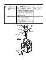
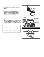
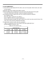
2-2-5 CONNECTING ROD

(1) Turn crankshaft to bottom dead center, lightly tap

top of the piston until large end of the rod meet

crank pin.

(2) Install connecting rod cap to connecting rod.

Attach connecting rod cap to connecting rod so

that the "MA" marking is faced upwards and the

splasher is located on the left-hand side.

Tighten connecting rod bolts to the specification.

M5 x 25 mm connecting rod bolt : 2 pcs.

(3) Check for free movement of connecting rod by

turning crankshaft slowly.

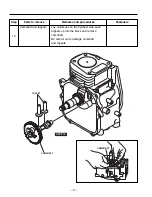
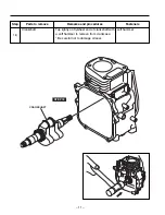
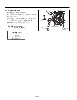
2-2-6 TAPPETS AND CAMSHAFT

(1) Oil the tappets and install them.

Push in fully to avoid damage during 

camshaft installation. 

(2) Lubricate bearing surfaces of camshaft.

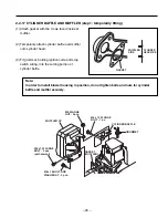
(3) Align the timing mark on crankshaft gear with the

timing mark on camshaft and install camshaft in

the crankcase.

CAUTION: 
Incorrect valve timing will cause malfunction
of the engine.

Tightening torque

6 - 8 N•m

(60 - 80 kgf•cm)

(4.3 - 5.7 ft•lb.)

M

A

"MA" MARK

SPLASHER
LEFT SIDE

TIMING MARK

CRANKSHAFT 
GEAR

CAMSHAFT 

Summary of Contents for EHO9-2D

Page 1: ...LINE ENGINE CO LTD ADD 28 CHANGJIANG NORTH ROAD XINBEI DISTRICT CHANGZHOU JIANGSU CHINA Tel 86 519 85036812 Fax 86 519 85109259 Http www fcrrobin com 28 86 519 85036812 86 519 5109259 Http www fcrrobi...

Page 2: ...E DATA 4 1 CLEARANCE DATA AND LIMITS 33 4 2 TORQUE SPECIFICATIONS 38 4 3 OIL GRADE CHART 38 The specifications and information included in this manual were in effect at the time of printing FUJI HEAVY...

Page 3: ...e unleaded gasoline Gravity type Flywheel magneto solid state NGK BMR4A CHAMPION RCJ14 Recoil starter Centrifugal flyweight type Semi wet type 10 2 22 44 235 x 308 x 341 9 25 x 12 13 x 13 43 MODEL Typ...

Page 4: ...drain oil 2 To discharge oil quickly remove oil gauge 14 mm spanner 2 Adapter and Stiffener M8 x 25 4 pcs M8 x 30 2 pcs M8 nut washer spring washer 4 pcs 12 mm box spanner OIL GAUGE CP GASKET GASKET...

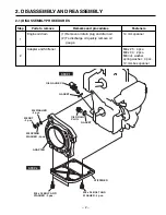
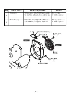
Page 5: ...OLT 3 pcs Step Parts to remove Remarks and procedures Fasteners 3 Recoil starter Remove recoil starter from blower housing Be careful of pulling direction of starter rope M6 x 8 3 pcs 10 mm box spanne...

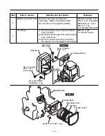
Page 6: ...wrench 6 Air cleaner 1 Remove cleaner cover first from cleaner base element 2 Remove breather pipe from cleaner base and rocker cover 3 Remove cleaner base from carburetor Be careful not to lose gaske...

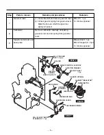
Page 7: ...rburetor carefully unhooking governor rod and rod spring from governor lever 9 Speed control lever and base plate M6 pivot bolt 1 pc M6 x 8 flange bolt 2 pcs 10 mm box spanner M6 x 8 FLANGE BOLT 2 pcs...

Page 8: ...g blower 3 Tap on flywheel end of crankshaft using aluminum bar to remove flywheel 4 Remove the key from crankshaft M14 nut springwasher 1 pc M6 x 12 4 pcs 19 mm socket wrench 10 mm box wrench 12 Spar...

Page 9: ...ox spanner 14 Cylinder head 1 Remove cylinder head and gasket from crankcase 2 Remove push rods from cylinder M8 x 55 2 pcs M8 x 55 x 12 5 2 pcs 10 12 mm box spanner or box wrench PUSH ROD PIPE KNOCK...

Page 10: ...res Fasteners 15 Main bearing cover Be careful not to damage the oil seal Use a soft hammer and evenly tap around outer surface of cover M6 x 30 9 pcs 10 mm box spanner soft hammer MAIN BEARING COVER...

Page 11: ...Remarks and procedures Fasteners 16 Camshaft and tappets Lay carnkcase on the flywheel side push tappets up into the block and remove camshaft Be careful not to damage camshaft and tappets CAMSHAFT T...
Page 12: ...pe off all carbon deposits that might interfere with removal of piston from upper end of cylinder M5 x 25 2 pcs 8 mm box spanner Piston and piston pin 1 Remove clips and piston pin to remove connectin...

Page 13: ...rts to remove Remarks and procedures Fasteners 18 Crankshaft Tap lightly on flywheel end of crankshaft with a soft hammer to remove from crankcase Be careful not to damage oil seal soft hammer CRANKSH...

Page 14: ...pring retainer and valve spring 2 Remove intake and exhaust valves from cylinder head Clean carbon and gum deposit from the valves valve seats ports and guides Inspect valves valve seats and guides 10...

Page 15: ...nd nuts to specification refer to the TORQUE SPECIFICATIONS See page 38 7 Apply oil to rotating and sliding portions 8 Check and adjust clearances and end plays where specified in this manual 9 When m...

Page 16: ...ring only far enough to slip over piston and into correct groove Use care not to distort ring Install top and second ring with punched mark beside the gap face upward OPEN ENDS OF PISTON RING 3 2 1 3...

Page 17: ...Install piston and connecting rod assembly into cylinder Use a piston ring compressor to hold piston rings The MA mark of the connecting rod is to face the flywheel side of the engine when assembled P...

Page 18: ...x 25 mm connecting rod bolt 2 pcs 3 Check for free movement of connecting rod by turning crankshaft slowly 2 2 6 TAPPETS AND CAMSHAFT 1 Oil the tappets and install them Push in fully to avoid damage d...

Page 19: ...earing 2 Measure the depth B From the mating surface to the crank gear B A SIDE CLEARANCE mm SIDE CLEARANCE 0 2 mm THICKNESS OF CRANKSHAFT SHIM mm B A SIDE CLEARANCE in SIDE CLEARANCE 0 008 in THICKNE...

Page 20: ...and bearing surfaces Coat the suface of the main bearing cover with sealant Three bond 1280B or 1216 Place spacer chosen in STEP 1 on crankshaft Use an oil seal guide when installing the main bearing...

Page 21: ...specifications See SERVICE DATA Draw valve guides out and press new guides in Refer to SERVICE DATA for clearance specifications After replacing valves and guides lap valves in place until a uniform r...

Page 22: ...ankcase Removal of the main bearing cover is necessary to get them out 2 Apply oil to rocker arms and assemble them to cylinder head using pivot bolt and nut GASKET PUSH ROD BOLT PIVOT 2 pcs COLLET VA...

Page 23: ...Tighten the nut on rocker arm 3 Install rocker cover and gasket M6 x 75 mm bolt 4 pcs Tightening torque 6 5 9 5 N m 65 95 kgf cm 4 7 6 8 ft lb Note Check and adjust valve clearance while engine is co...

Page 24: ...m flange bolt 4 pcs 2 Install the flywheel to crankshaft M6 x 00 mm flange bolt 4 pcs 3 Tighten crankshaft nut with locking pliers adopted as shown in the illustration M14 nut 1 pc Tightening torque 4...

Page 25: ...n of ignition coil and the location of code Adjust air gap between ignition coil and flywheel using a thickness gauge and tighten bolts M6 x 25 mm bolt and washer 2 pcs Tightening torque 7 9 N m 70 90...

Page 26: ...overnor lever and speed control lever 5 Install insulator and gaskets for carburetor to cylinder head 6 Install carburetor to cylinder head hooking governor rod to governor lever and throttle lever of...

Page 27: ...elf lock nut Check that the governor lever is pulled by the governor spring and carburetor throttle valve is fully open 2 Turn the governor shaft clockwise all the way using a screw driver and tighten...

Page 28: ...ignition code and stop switch wiring into the cutting portion of cylinder baffle Note In order to install blower housing in position do not tighten bolts and nuts for cylinder baffle and muffler secu...

Page 29: ...fler securely M6 x 14 mm flange bolt 1 pc cylinder buffle M8 x 16 mm bolt and washer 2 pcs crankcase boss M6 x 14 mm flange bolt 2 pcs exhaust port M8 flange nut 2 pcs upper bracket Tightening torque...

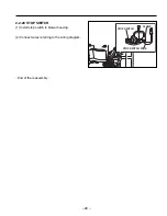
Page 30: ...28 2 2 20 STOP SWITCH 1 Install stop switch to blower housing 2 Connect wires referring to the wiring diagram End of the reassembly CLAMP STOP SWITCH WIRE STOP SWITCH...

Page 31: ...hort period of time While the engine is being tested check for oil leaks Make final carburetor adjustment and regulate the engine operating speed 2 4 ENGINE SPEED ADJUSTMENT High speed side Engine spe...

Page 32: ...rk plug Improper spark plug gap Insulation defect Carbon deposits 2 Ignition coil Insulation defect or discontinuity Poor contact or broken wire Adjust the gap Replace Clean Replace Repair or replace...

Page 33: ...eel magneto Replace Replace Replace Adjust 4 Poor quality gasoline or water in gasoline 1 Carburetor clogged 2 Fuel strainer and or hose clogged 3 Air in fuel lines Replace Overhaul clean Clean or rep...

Page 34: ...ose main bearing cover bolts Tighten 4 Faulty main bearing cover gasket Replace 5 Crankshaft oil seal front rear defect Repair or replace 2 Piston ring seizure wear or poor contact Replace 3 Excessive...

Page 35: ...TD 1st reboring 2nd reboring 5 500 5 518 0 2165 0 2172 Ditto 51 250 51 269 2 0177 2 0185 51 500 51 519 2 0276 2 0283 CYLINDER HEAD Flatness To be rebored when the difference between max and min of dia...

Page 36: ...1 11 035 0 4327 0 4344 0 25 0 010 0 010 0 049 0 0004 0 0019 1 5 0 0591 Top 0 15 0 35 0 006 0 014 2nd 0 35 0 55 0 014 0 022 PISTON Ring groove side clearance 10 960 0 4315 10 992 11 000 0 4328 0 4331 C...

Page 37: ...CONNECTING ROD Big end inside dia 0 12 0 0047 0 010 0 029 0 0004 0 0011 Clearance between small end and piston pin Big end side clearance D1 D2 19 988 19 997 0 7869 0 7873 20 85 0 821 20 967 20 980 0...

Page 38: ...ht IN and EX 5 35 0 2106 5 426 5 444 0 2136 0 2143 5 35 0 2106 5 440 5 455 0 2142 0 2148 IN EX 0 3 0 012 0 056 0 092 0 0022 0 0036 0 3 0 012 0 045 0 078 0 0018 0 0031 Clearance between valve stem dia...

Page 39: ...5 0 055 0 0010 0 0022 TAPPET Stem outside dia 26 7 1 05 VALVE SPRING FREE LENGTH a 90 b 0 8 1 1 0 031 0 043 2 0 0 079 Guide inside dia VALVE SEAT ANGLE IN and EX Valve cutter angle a Valve contact wid...

Page 40: ...50 8 5 10 5 85 105 6 1 7 6 17 19 170 190 12 3 13 7 170 190 17 19 12 3 13 7 10 12 100 120 7 2 8 7 12 15 120 150 8 7 10 9 230 250 23 25 16 6 18 1 ITEMS Use oil classified as SE or higher SG SH or SJ is...

Page 41: ...LINE ENGINE CO LTD ADD 28 CHANGJIANG NORTH ROAD XINBEI DISTRICT CHANGZHOU JIANGSU CHINA Tel 86 519 85036812 Fax 86 519 85109259 Http www fcrrobin com 28 86 519 85036812 86 519 5109259 Http www fcrrobi...

Reviews: